> ## Documentation Index
> Fetch the complete documentation index at: https://docs.supplyline.com/docs/llms.txt
> Use this file to discover all available pages before exploring further.
# Installation
> Mounting, piping connections, and typical installation configurations for MTC DICE dosing modules
# Installation
Source: [DICE IOM Manual V12E](https://supplyline.com/assets/MTC-IOM_DICE-DS-DM-Operating-Manual-V12E.pdf), Section: Installation, Pages: 14–17
Always use the proper tool for each step. Never use a pipe wrench on the DICE module.
## Mounting
Source: [DICE IOM Manual V12E](https://supplyline.com/assets/MTC-IOM_DICE-DS-DM-Operating-Manual-V12E.pdf#page=14), Section: Mounting, Page: 14
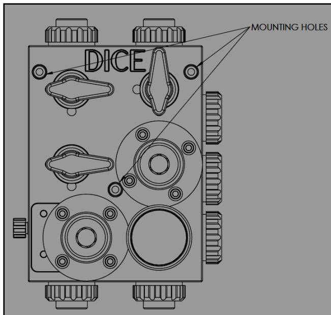
The DICE module mounts to a planar surface using three mounting holes on the rear face.
### Requirements
* Mount with the **injection port facing upward**
* Keep the module **level** to prevent trapped air
* Allow sufficient clearance for maintenance access
 ### Mounting Procedure
Place the three provided washers (part 31) between each mounting hole and the mounting surface. The washers isolate the module body from the mounting surface.
Confirm no corner of the module touches the mounting surface. Only the washers should contact the surface.
Mounting holes accept M6 or 1/4" socket head screws. Torque: **35 in-lb**.
### Mounting Procedure
Place the three provided washers (part 31) between each mounting hole and the mounting surface. The washers isolate the module body from the mounting surface.
Confirm no corner of the module touches the mounting surface. Only the washers should contact the surface.
Mounting holes accept M6 or 1/4" socket head screws. Torque: **35 in-lb**.
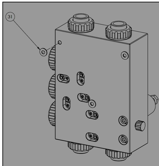 Using the washers prevents mechanical stress on the DICE body. Stress from improper mounting can cause part failure.
## Connections
Source: [DICE IOM Manual V12E](https://supplyline.com/assets/MTC-IOM_DICE-DS-DM-Operating-Manual-V12E.pdf#page=15), Section: Connections, Page: 15
DICE uses a mushroom nut connection system that allows tool-free assembly and disassembly.
### Connection Assembly
Slide the mushroom nut (25) onto the connector (26/27/28). Insert the pipe or tubing into the connector.
Ensure pipes and tubing are perfectly aligned with the module port. Misalignment causes mechanical stress that can lead to failure.
Confirm the O-ring (30) is properly seated in the connector groove.
Thread the mushroom nut onto the port and tighten **by hand only**. Do not use tools.
Using the washers prevents mechanical stress on the DICE body. Stress from improper mounting can cause part failure.
## Connections
Source: [DICE IOM Manual V12E](https://supplyline.com/assets/MTC-IOM_DICE-DS-DM-Operating-Manual-V12E.pdf#page=15), Section: Connections, Page: 15
DICE uses a mushroom nut connection system that allows tool-free assembly and disassembly.
### Connection Assembly
Slide the mushroom nut (25) onto the connector (26/27/28). Insert the pipe or tubing into the connector.
Ensure pipes and tubing are perfectly aligned with the module port. Misalignment causes mechanical stress that can lead to failure.
Confirm the O-ring (30) is properly seated in the connector groove.
Thread the mushroom nut onto the port and tighten **by hand only**. Do not use tools.
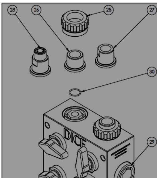 | Part | Component |
| ---- | ---------------- |
| 25 | Mushroom nut |
| 26 | Socket connector |
| 27 | NPT connector |
| 28 | Hose connector |
| 29 | Cap |
| 30 | O-ring |
If connecting accessories (pulsation dampener, flow monitor, etc.) to auxiliary ports, provide independent support for the accessory. The DICE module is not designed to support accessory weight.
## Typical Installations
Source: [DICE IOM Manual V12E](https://supplyline.com/assets/MTC-IOM_DICE-DS-DM-Operating-Manual-V12E.pdf#page=16), Section: Installation Schematics, Pages: 16–17
The DS configuration uses suction lift from a chemical tank located below the dosing system.
| Part | Component |
| ---- | ---------------- |
| 25 | Mushroom nut |
| 26 | Socket connector |
| 27 | NPT connector |
| 28 | Hose connector |
| 29 | Cap |
| 30 | O-ring |
If connecting accessories (pulsation dampener, flow monitor, etc.) to auxiliary ports, provide independent support for the accessory. The DICE module is not designed to support accessory weight.
## Typical Installations
Source: [DICE IOM Manual V12E](https://supplyline.com/assets/MTC-IOM_DICE-DS-DM-Operating-Manual-V12E.pdf#page=16), Section: Installation Schematics, Pages: 16–17
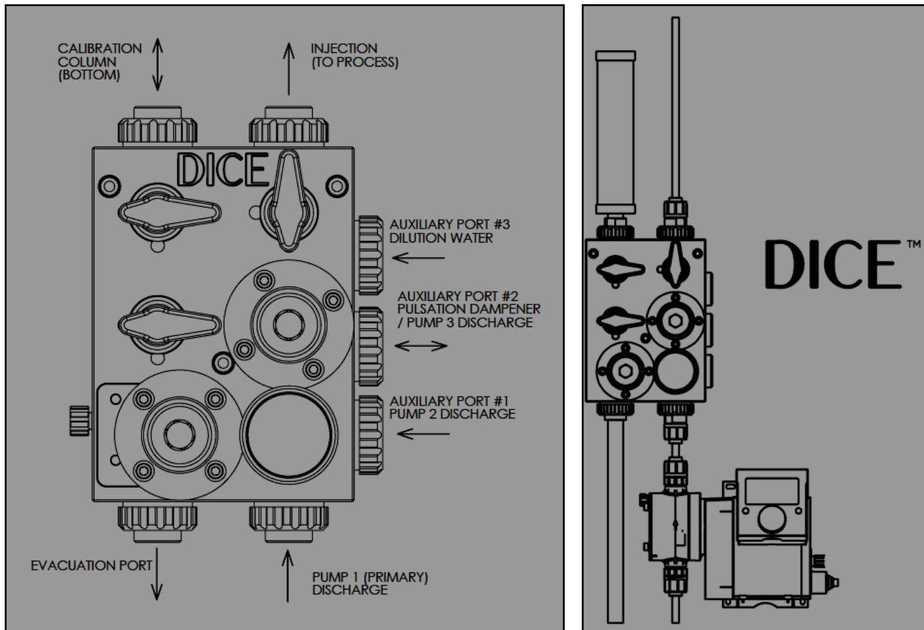
The DS configuration uses suction lift from a chemical tank located below the dosing system.
 ### DS Component Layout
| Component | Function |
| ----------------------- | -------------------------------- |
| Pump input | Suction from chemical tank |
| Pump output | Feeds DICE module |
| Calibration column | Connects to module input line |
| PRV | Overpressure protection |
| Bleed valve | Priming assist, depressurization |
| PI (Pressure Indicator) | System pressure monitoring |
| BPV | Maintains discharge pressure |
| Injection port | To process |
| Auxiliary ports 1, 2, 3 | Secondary pumps, accessories |
| Evacuation port | Drains to chemical tank |
### DS Port Configuration
| Port | Name | Typical Use |
| ----------- | ------------------ | -------------------- |
| Top center | Injection | To process |
| Top left | Calibration column | Calibration cylinder |
| Bottom left | Evacuation | Drain to tank |
| Side | Auxiliary 1 | Pump 2 discharge |
| Side | Auxiliary 2 | Pulsation dampener |
| Side | Auxiliary 3 | Dilution water |
| Side | Pump input | From pump 1 |
The DM configuration supports both suction lift and flooded suction applications.
### DS Component Layout
| Component | Function |
| ----------------------- | -------------------------------- |
| Pump input | Suction from chemical tank |
| Pump output | Feeds DICE module |
| Calibration column | Connects to module input line |
| PRV | Overpressure protection |
| Bleed valve | Priming assist, depressurization |
| PI (Pressure Indicator) | System pressure monitoring |
| BPV | Maintains discharge pressure |
| Injection port | To process |
| Auxiliary ports 1, 2, 3 | Secondary pumps, accessories |
| Evacuation port | Drains to chemical tank |
### DS Port Configuration
| Port | Name | Typical Use |
| ----------- | ------------------ | -------------------- |
| Top center | Injection | To process |
| Top left | Calibration column | Calibration cylinder |
| Bottom left | Evacuation | Drain to tank |
| Side | Auxiliary 1 | Pump 2 discharge |
| Side | Auxiliary 2 | Pulsation dampener |
| Side | Auxiliary 3 | Dilution water |
| Side | Pump input | From pump 1 |
The DM configuration supports both suction lift and flooded suction applications.
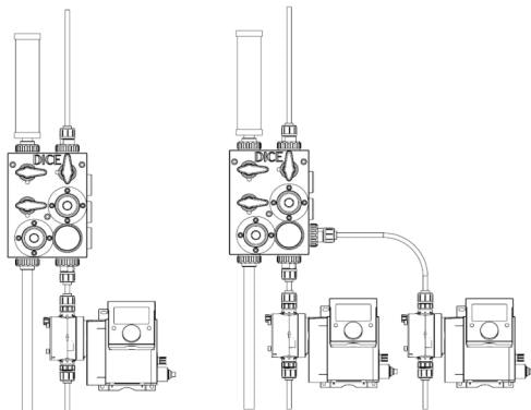 ### DM Component Layout
| Component | Function |
| ----------------------- | --------------------------------------------- |
| Pump input | Suction from chemical tank |
| Pump output | Feeds DICE module |
| Calibration column | Connects to module input line |
| Auxiliary port 4 | Additional input connection |
| PRV | Overpressure protection |
| Bleed valve | Priming assist, depressurization |
| PI (Pressure Indicator) | System pressure monitoring |
| BPV | Maintains discharge pressure |
| Injection port | To process |
| Auxiliary ports 1, 2, 3 | Secondary pumps, accessories |
| Return options | Option 1: Pump return. Option 2: Back to tank |
### DM Advantages
* **Separation valve (4)**: Isolates suction side during calibration
* **Fourth auxiliary port**: Additional connection point on suction side
* **Return path options**: Route overflow to pump return or chemical tank
### DM Port Configuration
Includes all DS ports plus:
| Port | Name | Typical Use |
| ---- | ---------------- | ----------------------- |
| Side | Auxiliary 4 | Additional input/output |
| — | Separation valve | Suction isolation |
## Installation Examples
Mount the DICE module vertically above the dosing pump. This configuration:
* Minimizes piping runs
* Facilitates gas evacuation
* Provides clear access for operation
Connect two dosing pumps to auxiliary ports for redundancy. Each pump should include an integral check valve. The DICE module consolidates both pump outputs through a single back pressure and relief system.
Connect a pulsation dampener to an auxiliary port when using diaphragm pumps that create significant pulsation. Support the dampener independently.
***
## Related Products
1/2" module for suction lift applications
1/2" and 1" modules for flooded suction
## Sources
Pages 14–17 • July 2022
### DM Component Layout
| Component | Function |
| ----------------------- | --------------------------------------------- |
| Pump input | Suction from chemical tank |
| Pump output | Feeds DICE module |
| Calibration column | Connects to module input line |
| Auxiliary port 4 | Additional input connection |
| PRV | Overpressure protection |
| Bleed valve | Priming assist, depressurization |
| PI (Pressure Indicator) | System pressure monitoring |
| BPV | Maintains discharge pressure |
| Injection port | To process |
| Auxiliary ports 1, 2, 3 | Secondary pumps, accessories |
| Return options | Option 1: Pump return. Option 2: Back to tank |
### DM Advantages
* **Separation valve (4)**: Isolates suction side during calibration
* **Fourth auxiliary port**: Additional connection point on suction side
* **Return path options**: Route overflow to pump return or chemical tank
### DM Port Configuration
Includes all DS ports plus:
| Port | Name | Typical Use |
| ---- | ---------------- | ----------------------- |
| Side | Auxiliary 4 | Additional input/output |
| — | Separation valve | Suction isolation |
## Installation Examples
Mount the DICE module vertically above the dosing pump. This configuration:
* Minimizes piping runs
* Facilitates gas evacuation
* Provides clear access for operation
Connect two dosing pumps to auxiliary ports for redundancy. Each pump should include an integral check valve. The DICE module consolidates both pump outputs through a single back pressure and relief system.
Connect a pulsation dampener to an auxiliary port when using diaphragm pumps that create significant pulsation. Support the dampener independently.
***
## Related Products
1/2" module for suction lift applications
1/2" and 1" modules for flooded suction
## Sources
Pages 14–17 • July 2022