> ## Documentation Index
> Fetch the complete documentation index at: https://docs.supplyline.com/docs/llms.txt
> Use this file to discover all available pages before exploring further.
# Maintenance
> Disassembly, assembly, and periodic maintenance procedures for MTC DICE dosing modules
# Maintenance
Source: [DICE IOM Manual V12E](https://supplyline.com/assets/MTC-IOM_DICE-DS-DM-Operating-Manual-V12E.pdf), Pages: 31–38
**Before any disassembly:**
* Turn off electrical power
* Depressurize the system completely
* Release both regulating valves
* Vent fluids to a safe area
* Flush all fluids from the module
* Wear protective gloves, glasses, and clothing
* Refer to the MSDS for all chemicals used
## Ball Valve Disassembly
 ### Preparation
1. Release inner housing pressure by partially opening the ball valve
2. Close all ball valves before disassembly
3. Apply axial force when using sockets to prevent skipping
### Disassembly Procedure
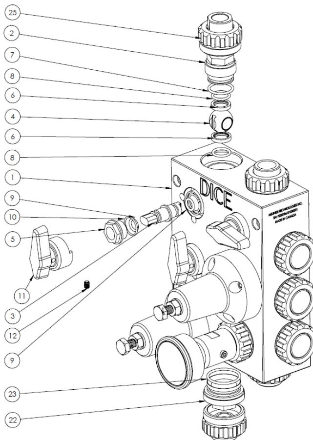
Loosen the mushroom nut (25) and remove the connector (26/27/28).
Loosen and remove the sleeve cone (22) with a 27mm socket. *Only for evacuation ball valve or center ball valve on DM.*
Loosen and remove the ball valve carrier (2) with a 27mm socket.
Remove the ball (4) from the valve housing.
Remove ball valve seats (6) from the carrier (2) and block (1). Mark the outward-facing side of each seat with a marker to ensure correct reassembly orientation.
Loosen the handle set screw (12) with a 3mm Allen key. Remove handle (11).
Loosen the stem nut (5) with a 22mm socket. Remove stem nut (5) and stem (3) from block.
### Assembly Procedure
Reverse the disassembly steps, observing these requirements:
| Component | Torque | Notes |
| --------------------- | ------------------ | ---------------------------------- |
| Carrier (2) | 20 in-lb (dynamic) | Verify position from block surface |
| Stem nut (5) | 30 in-lb | — |
| Handle set screw (12) | 60 oz-in | — |
| Valve | Distance from Block Surface |
| ----------------------------- | ---------------------------- |
| Calibration column, Injection | 0 mm (flush) ± 0.25 mm |
| Evacuation | 71.6 mm (2.820 in) ± 0.25 mm |
* When reinstalling seats (6), ensure the marked side faces away from the ball
* If using new seats, operate the ball valve 5 times after torquing the carrier
* Verify O-ring (31) is positioned in the groove when reinstalling connectors
* **Grease all O-rings** with clear food-grade silicone NLGI #1 grease before assembly
* 27mm socket (carrier, sleeve cone)
* 22mm socket (stem nut)
* 3mm Allen key (handle set screw)
* Torque wrench
## Pressure Relief and Back Pressure Valve Disassembly
### Preparation
1. Release inner housing pressure by partially opening the ball valve
2. Close all ball valves before disassembly
3. Apply axial force when using sockets to prevent skipping
### Disassembly Procedure
Loosen the mushroom nut (25) and remove the connector (26/27/28).
Loosen and remove the sleeve cone (22) with a 27mm socket. *Only for evacuation ball valve or center ball valve on DM.*
Loosen and remove the ball valve carrier (2) with a 27mm socket.
Remove the ball (4) from the valve housing.
Remove ball valve seats (6) from the carrier (2) and block (1). Mark the outward-facing side of each seat with a marker to ensure correct reassembly orientation.
Loosen the handle set screw (12) with a 3mm Allen key. Remove handle (11).
Loosen the stem nut (5) with a 22mm socket. Remove stem nut (5) and stem (3) from block.
### Assembly Procedure
Reverse the disassembly steps, observing these requirements:
| Component | Torque | Notes |
| --------------------- | ------------------ | ---------------------------------- |
| Carrier (2) | 20 in-lb (dynamic) | Verify position from block surface |
| Stem nut (5) | 30 in-lb | — |
| Handle set screw (12) | 60 oz-in | — |
| Valve | Distance from Block Surface |
| ----------------------------- | ---------------------------- |
| Calibration column, Injection | 0 mm (flush) ± 0.25 mm |
| Evacuation | 71.6 mm (2.820 in) ± 0.25 mm |
* When reinstalling seats (6), ensure the marked side faces away from the ball
* If using new seats, operate the ball valve 5 times after torquing the carrier
* Verify O-ring (31) is positioned in the groove when reinstalling connectors
* **Grease all O-rings** with clear food-grade silicone NLGI #1 grease before assembly
* 27mm socket (carrier, sleeve cone)
* 22mm socket (stem nut)
* 3mm Allen key (handle set screw)
* Torque wrench
## Pressure Relief and Back Pressure Valve Disassembly
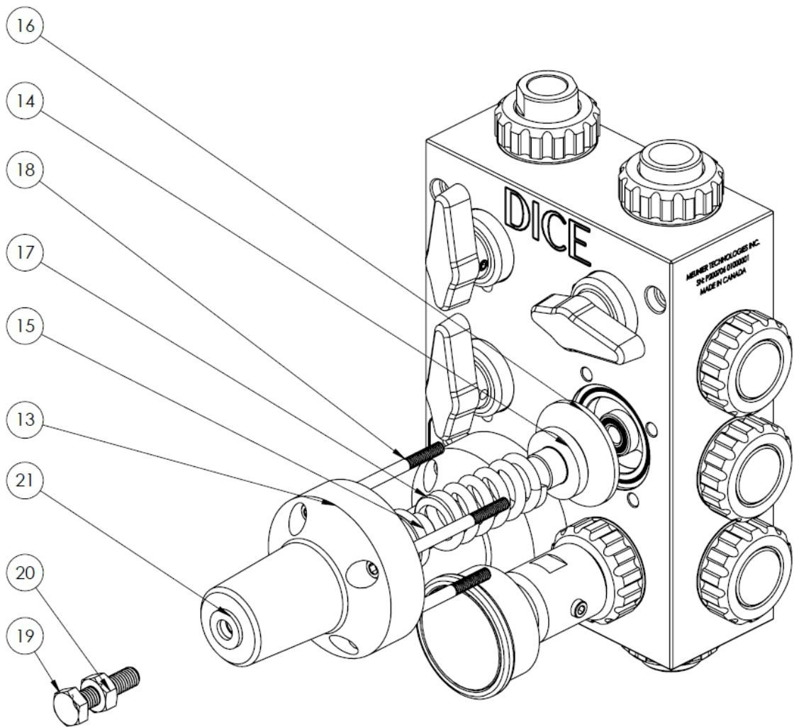 | Part | Description |
| ---- | --------------------- |
| 13 | Regulating valve body |
| 14 | Bottom seat |
| 15 | Top seat |
| 16 | Diaphragm |
| 17 | Spring |
| 18 | Mounting bolts (4) |
| 19 | Adjustment screw |
| 20 | Counter nut |
| 21 | Washer |
### Disassembly Procedure
Using a 17mm socket, loosen and remove the adjustment screw (19) along with counter nut (20) and washer (21).
Remove the four mounting bolts (18) with a 5mm Allen key.
Lift off the regulating valve body (13).
Remove the spring (17), top seat (15), and bottom seat (14) as a group.
Remove the diaphragm (16) from the block (1).
Inspect all parts and replace as needed.
### Assembly Procedure
Reverse disassembly steps, following the bolt tightening pattern:
| Part | Description |
| ---- | --------------------- |
| 13 | Regulating valve body |
| 14 | Bottom seat |
| 15 | Top seat |
| 16 | Diaphragm |
| 17 | Spring |
| 18 | Mounting bolts (4) |
| 19 | Adjustment screw |
| 20 | Counter nut |
| 21 | Washer |
### Disassembly Procedure
Using a 17mm socket, loosen and remove the adjustment screw (19) along with counter nut (20) and washer (21).
Remove the four mounting bolts (18) with a 5mm Allen key.
Lift off the regulating valve body (13).
Remove the spring (17), top seat (15), and bottom seat (14) as a group.
Remove the diaphragm (16) from the block (1).
Inspect all parts and replace as needed.
### Assembly Procedure
Reverse disassembly steps, following the bolt tightening pattern:
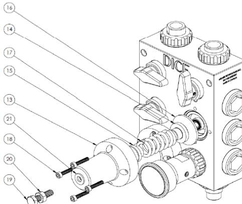 **Tightening sequence** (star pattern): Right → Left → Top → Bottom
| Component | Torque |
| ------------------- | -------- |
| Mounting bolts (18) | 35 in-lb |
Use a filler gauge at four points around the valve body to confirm no gap exists between the regulating valve body (13) and block (1).
* 17mm socket (adjustment screw)
* 5mm Allen key (mounting bolts)
* Torque wrench
* Filler gauge
After reassembly, perform valve adjustment per the [Startup](/docs/mtc/dice/startup) procedures.
## Bleed Valve Maintenance
**Tightening sequence** (star pattern): Right → Left → Top → Bottom
| Component | Torque |
| ------------------- | -------- |
| Mounting bolts (18) | 35 in-lb |
Use a filler gauge at four points around the valve body to confirm no gap exists between the regulating valve body (13) and block (1).
* 17mm socket (adjustment screw)
* 5mm Allen key (mounting bolts)
* Torque wrench
* Filler gauge
After reassembly, perform valve adjustment per the [Startup](/docs/mtc/dice/startup) procedures.
## Bleed Valve Maintenance
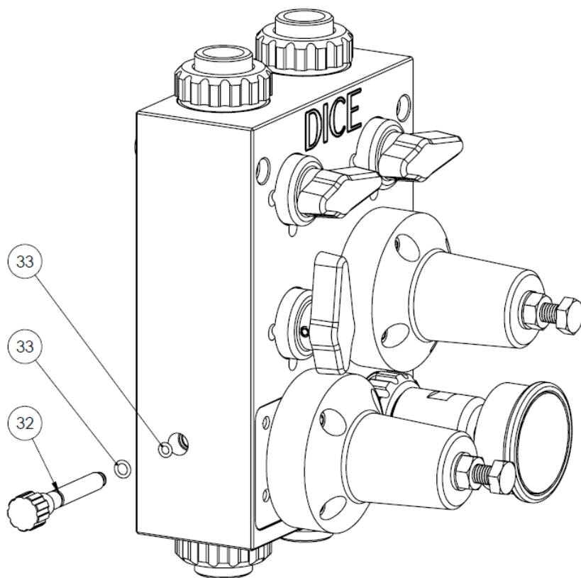 **Disassembly**: Completely unscrew and pull the bleed valve (32) from the module. The bleed valve has two replaceable O-rings (33).
**Assembly**: Push and screw the bleed valve completely into the module.
Do not use tools on the bleed valve. Hand-tighten only.
## Pressure Indicator and Isolator
No periodic maintenance is required on the pressure indicator and isolator assembly.
**Disassembly**: Completely unscrew and pull the bleed valve (32) from the module. The bleed valve has two replaceable O-rings (33).
**Assembly**: Push and screw the bleed valve completely into the module.
Do not use tools on the bleed valve. Hand-tighten only.
## Pressure Indicator and Isolator
No periodic maintenance is required on the pressure indicator and isolator assembly.
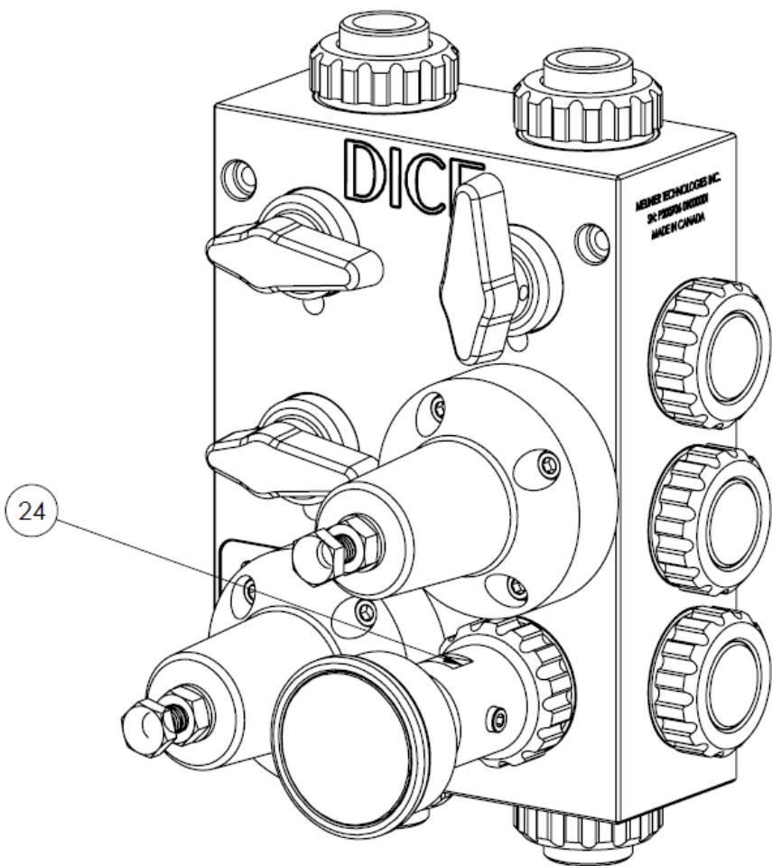 If the pressure indicator or isolator fails:
1. Depressurize the module completely
2. Remove the isolator and pressure indicator assembly (24) from the block—hand-loosen only
3. Contact supplier with RMA form
4. Ship assembly for repair
**Do not disassemble the isolator on site.** The isolator filling requires specialized tools and is performed by factory technicians.
## Periodic Maintenance Schedule
* Visual inspection for leaks at all connection points
* Verify system operating pressure matches back pressure set point
* Check for chemical deposits or crystallization
**Ball valve operation**: Fully open and close each ball valve to prevent seat damage from extended static positions. Record each operation.
Before operating valves, release module pressure by closing the outlet port valve and opening the evacuation valve. Operating valves under pressure can cause chemical spillage from the calibration column.
**Regulating valve inspection**: Fully inspect back pressure and pressure relief valve diaphragms. Replace diaphragms showing signs of wear.
Clean the DICE module when deposits, scaling, or crystals obstruct flow. Cleaning frequency depends on:
* Chemical properties
* Operating conditions
* Environment
Cleaning fluids must be compatible with both the dosed chemical and all system materials. Consult your chemical supplier.
## Spare Parts
To order spare parts, provide:
* Module serial number (engraved on block)
* Part number from the [Parts List](/docs/mtc/dice/parts)
***
## Related Products
1/2" module for suction lift applications
1/2" and 1" modules for flooded suction
## Sources
Pages 31–38 • July 2022
If the pressure indicator or isolator fails:
1. Depressurize the module completely
2. Remove the isolator and pressure indicator assembly (24) from the block—hand-loosen only
3. Contact supplier with RMA form
4. Ship assembly for repair
**Do not disassemble the isolator on site.** The isolator filling requires specialized tools and is performed by factory technicians.
## Periodic Maintenance Schedule
* Visual inspection for leaks at all connection points
* Verify system operating pressure matches back pressure set point
* Check for chemical deposits or crystallization
**Ball valve operation**: Fully open and close each ball valve to prevent seat damage from extended static positions. Record each operation.
Before operating valves, release module pressure by closing the outlet port valve and opening the evacuation valve. Operating valves under pressure can cause chemical spillage from the calibration column.
**Regulating valve inspection**: Fully inspect back pressure and pressure relief valve diaphragms. Replace diaphragms showing signs of wear.
Clean the DICE module when deposits, scaling, or crystals obstruct flow. Cleaning frequency depends on:
* Chemical properties
* Operating conditions
* Environment
Cleaning fluids must be compatible with both the dosed chemical and all system materials. Consult your chemical supplier.
## Spare Parts
To order spare parts, provide:
* Module serial number (engraved on block)
* Part number from the [Parts List](/docs/mtc/dice/parts)
***
## Related Products
1/2" module for suction lift applications
1/2" and 1" modules for flooded suction
## Sources
Pages 31–38 • July 2022