> ## Documentation Index
> Fetch the complete documentation index at: https://docs.supplyline.com/docs/llms.txt
> Use this file to discover all available pages before exploring further.
# Operation
> Normal operation, operating modes, ball valve guidance, and depressurization procedures for MTC DICE
# Operation
Source: [DICE IOM Manual V12E](https://supplyline.com/assets/MTC-IOM_DICE-DS-DM-Operating-Manual-V12E.pdf), Pages: 24–30
Use this section to confirm valve positions, operating modes, and safe depressurization steps.
## Normal Operation
During normal injection operation:
| Valve | Position |
| ------------------------ | -------- |
| Injection (1) | **Open** |
| Calibration column (2) | Closed |
| Evacuation (3) | Closed |
| Separation (4) — DM only | Closed |
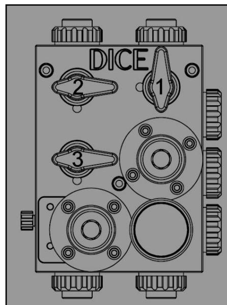 During normal operation, the pressure indicator should display the back pressure valve set point. If the reading differs significantly, refer to [Troubleshooting](/docs/mtc/dice/troubleshooting).
## Operating Modes
Chemical flows from the tank through the pump, into the DICE module, through the back pressure valve, and out the injection port to the process.
| Model | Flow Path | Return Path |
| ----- | ------------------------------------ | ------------------------------------- |
| DS | Tank → Pump → Module → BPV → Process | Bleed/PRV → Tank |
| DM | Tank → Pump → Module → BPV → Process | Option 1: Pump return. Option 2: Tank |
Chemical flows from the tank through the pump into the calibration column.
| Model | Valve Positions |
| ----- | ---------------------------------------------------------------------- |
| DS | Injection closed, Calibration open, Evacuation closed |
| DM | Injection closed, Calibration open, Evacuation closed, Separation open |
Calibration column contents drain through the evacuation path.
**DICE DS**: Fluid drains from calibration column through the module, past the PRV, through the bleed valve, and back to the chemical tank.
**DICE DM**: Same path with two return options:
* Option 1: Route to pump return
* Option 2: Route back to chemical tank
When system pressure exceeds the pressure relief valve set point, excess flow is directed through the PRV, past the bleed valve, and returned to the chemical tank (or pump return on DM Option 1).
This protects the system from overpressure conditions caused by blocked discharge lines or closed downstream valves.
## Ball Valve Guidelines
Ball valves are designed for **on/off service only**. Never leave valves partially open for extended periods.
During normal operation, the pressure indicator should display the back pressure valve set point. If the reading differs significantly, refer to [Troubleshooting](/docs/mtc/dice/troubleshooting).
## Operating Modes
Chemical flows from the tank through the pump, into the DICE module, through the back pressure valve, and out the injection port to the process.
| Model | Flow Path | Return Path |
| ----- | ------------------------------------ | ------------------------------------- |
| DS | Tank → Pump → Module → BPV → Process | Bleed/PRV → Tank |
| DM | Tank → Pump → Module → BPV → Process | Option 1: Pump return. Option 2: Tank |
Chemical flows from the tank through the pump into the calibration column.
| Model | Valve Positions |
| ----- | ---------------------------------------------------------------------- |
| DS | Injection closed, Calibration open, Evacuation closed |
| DM | Injection closed, Calibration open, Evacuation closed, Separation open |
Calibration column contents drain through the evacuation path.
**DICE DS**: Fluid drains from calibration column through the module, past the PRV, through the bleed valve, and back to the chemical tank.
**DICE DM**: Same path with two return options:
* Option 1: Route to pump return
* Option 2: Route back to chemical tank
When system pressure exceeds the pressure relief valve set point, excess flow is directed through the PRV, past the bleed valve, and returned to the chemical tank (or pump return on DM Option 1).
This protects the system from overpressure conditions caused by blocked discharge lines or closed downstream valves.
## Ball Valve Guidelines
Ball valves are designed for **on/off service only**. Never leave valves partially open for extended periods.
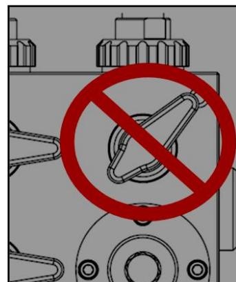 * Partial opening causes uneven wear on PTFE valve seats
* Damaged seats lead to leakage in the closed position
* Throttling reduces valve service life
**Best practices:**
* Always move valves to fully open or fully closed
* If a valve feels stiff, operate it several times to reseat
* Never force a valve—if excessive torque is required, refer to [Troubleshooting](/docs/mtc/dice/troubleshooting)
## Lockout Procedures
DICE modules can be ordered with optional lockout handles, or lockout kits can be purchased separately.
* Partial opening causes uneven wear on PTFE valve seats
* Damaged seats lead to leakage in the closed position
* Throttling reduces valve service life
**Best practices:**
* Always move valves to fully open or fully closed
* If a valve feels stiff, operate it several times to reseat
* Never force a valve—if excessive torque is required, refer to [Troubleshooting](/docs/mtc/dice/troubleshooting)
## Lockout Procedures
DICE modules can be ordered with optional lockout handles, or lockout kits can be purchased separately.
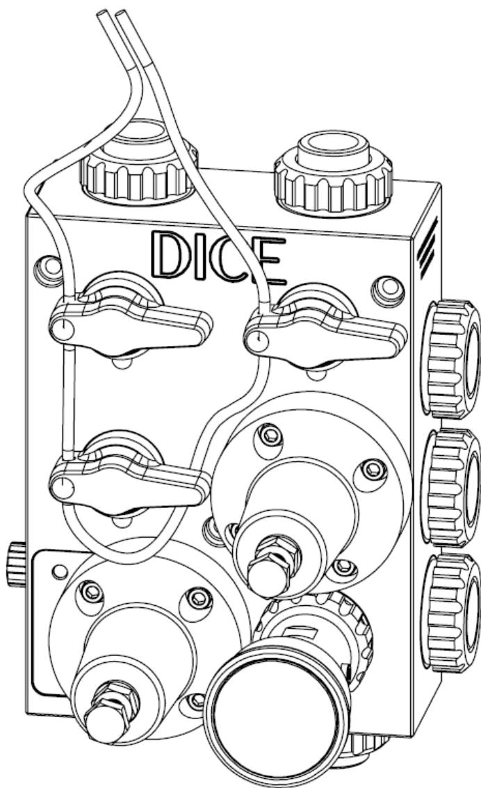 Set each ball valve to the required locked position (open or closed).
Ensure the locking ball device seats in the spherical groove on the block.
Insert the provided lockout wire through each handle.
Confirm each ball valve is locked and cannot be operated.
## Depressurizing the DICE Module
Before any maintenance, fully depressurize the module.
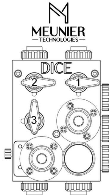
Close the injection ball valve (1) and calibration column ball valve (2).
Open the evacuation ball valve (3) to vent downstream pressure.
Set each ball valve to the required locked position (open or closed).
Ensure the locking ball device seats in the spherical groove on the block.
Insert the provided lockout wire through each handle.
Confirm each ball valve is locked and cannot be operated.
## Depressurizing the DICE Module
Before any maintenance, fully depressurize the module.
Close the injection ball valve (1) and calibration column ball valve (2).
Open the evacuation ball valve (3) to vent downstream pressure.
 Find the bleed valve (32) on the left side of the module.
Partially unscrew the bleed valve while watching the pressure indicator. Pressure should drop to zero.
Once depressurized, close the bleed valve.
Find the bleed valve (32) on the left side of the module.
Partially unscrew the bleed valve while watching the pressure indicator. Pressure should drop to zero.
Once depressurized, close the bleed valve.
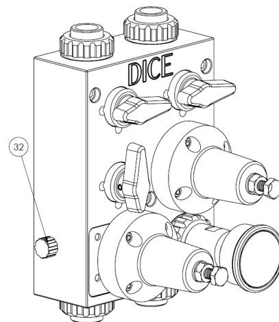 Do not use tools on the bleed valve. Hand-tighten only.
* This procedure depressurizes only the DICE internal cavities
* Chemical pressure may still exist downstream of closed ball valves (e.g., process pressure downstream of closed injection valve)
* Release all downstream pressure before disconnecting piping
* For flooded suction applications, drain the pump suction line before depressurizing the DICE module
The depressurizing procedure is informative and does not limit operator responsibility to verify absence of pressure before maintenance. Always confirm zero pressure before opening any connections.
***
## Related Products
1/2" module for suction lift applications
1/2" and 1" modules for flooded suction
## Sources
Pages 24–30 • July 2022
Do not use tools on the bleed valve. Hand-tighten only.
* This procedure depressurizes only the DICE internal cavities
* Chemical pressure may still exist downstream of closed ball valves (e.g., process pressure downstream of closed injection valve)
* Release all downstream pressure before disconnecting piping
* For flooded suction applications, drain the pump suction line before depressurizing the DICE module
The depressurizing procedure is informative and does not limit operator responsibility to verify absence of pressure before maintenance. Always confirm zero pressure before opening any connections.
***
## Related Products
1/2" module for suction lift applications
1/2" and 1" modules for flooded suction
## Sources
Pages 24–30 • July 2022