> ## Documentation Index
> Fetch the complete documentation index at: https://docs.supplyline.com/docs/llms.txt
> Use this file to discover all available pages before exploring further.
# Startup
> Pump priming, valve adjustment, and calibration procedures for MTC DICE dosing modules
# Startup
Source: [DICE IOM Manual V12E](https://supplyline.com/assets/MTC-IOM_DICE-DS-DM-Operating-Manual-V12E.pdf), Pages: 18–23
The module is internally pressurized and handles hazardous chemicals. Use appropriate PPE: protective gloves, glasses, and clothing. Refer to the MSDS for all fluids used.
If valves were factory preset (labeled with target pressure), skip the adjustment procedures and proceed to calibration.
## Pump Priming
The bleed valve (32) on the left side of the DICE module helps evacuate trapped gas between the pump outlet and back pressure valve.
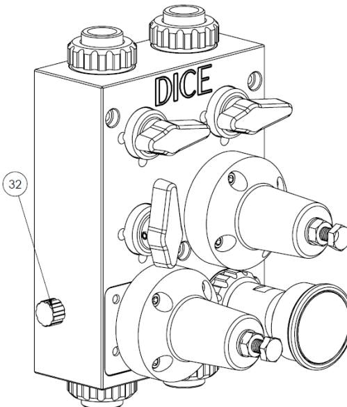 Begin pump cycling while observing for flow.
Partially unscrew the bleed valve (32) until fluid begins passing through. Only slight opening is needed—do not fully unscrew.
Once fluid flows, close the bleed valve and proceed with setup.
The bleed valve can also assist if the pump loses prime during normal operation.
## Pressure Relief Valve Adjustment
Begin pump cycling while observing for flow.
Partially unscrew the bleed valve (32) until fluid begins passing through. Only slight opening is needed—do not fully unscrew.
Once fluid flows, close the bleed valve and proceed with setup.
The bleed valve can also assist if the pump loses prime during normal operation.
## Pressure Relief Valve Adjustment
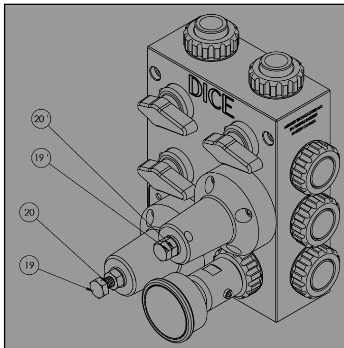 Set all three (DS) or four (DM) ball valves to the closed position.
Screw the back pressure adjustment screw (19') completely in (clockwise).
Run the pump until fluid passes through the pressure relief valve into the evacuation port.
Use adjustment screw (19) to obtain the desired relief pressure. Clockwise increases the set pressure.
Tighten counter nut (20). Max torque: **35 in-lb**.
Stop the pump and slowly open the evacuation ball valve to release system pressure.
## Back Pressure Valve Adjustment
Set all three (DS) or four (DM) ball valves to the closed position.
Screw the back pressure adjustment screw (19') completely in (clockwise).
Run the pump until fluid passes through the pressure relief valve into the evacuation port.
Use adjustment screw (19) to obtain the desired relief pressure. Clockwise increases the set pressure.
Tighten counter nut (20). Max torque: **35 in-lb**.
Stop the pump and slowly open the evacuation ball valve to release system pressure.
## Back Pressure Valve Adjustment
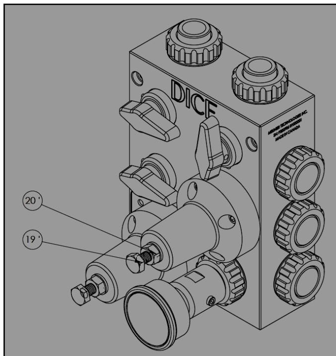 Close the evacuation and calibration column valves. Open the injection valve.
Run the pump until fluid passes through the back pressure valve.
Initially unscrew adjustment screw (19'), then adjust to desired pressure. Clockwise increases the set pressure.
Tighten counter nut (20'). Max torque: **35 in-lb**.
Set back pressure to **20-30 psi above process pressure** for optimal check valve operation and siphon prevention.
| Part | Description | Location |
| ---- | -------------------------------- | ------------ |
| 19 | Pressure relief adjustment screw | Top valve |
| 19' | Back pressure adjustment screw | Bottom valve |
| 20 | Pressure relief counter nut | Top valve |
| 20' | Back pressure counter nut | Bottom valve |
## Dosing Pump Calibration
Complete back pressure and pressure relief valve adjustment before calibrating the pump.
Close the evacuation valve (3) and injection valve (1). Open the calibration column valve (2).
Follow your dosing pump manufacturer's calibration procedure using the calibration column.
Open the evacuation valve (3) to empty the calibration column. Vent the top of the calibration column to enable complete drainage.
Close the evacuation valve (3) and calibration column valve (2). Open the injection valve (1).
### DS Valve Positions
| Mode | Valve 1 (Injection) | Valve 2 (Calibration) | Valve 3 (Evacuation) |
| ---------------- | ------------------- | --------------------- | -------------------- |
| Calibration | Closed | Open | Closed |
| Draining | Closed | Closed | Open |
| Normal operation | Open | Closed | Closed |
Close the evacuation and calibration column valves. Open the injection valve.
Run the pump until fluid passes through the back pressure valve.
Initially unscrew adjustment screw (19'), then adjust to desired pressure. Clockwise increases the set pressure.
Tighten counter nut (20'). Max torque: **35 in-lb**.
Set back pressure to **20-30 psi above process pressure** for optimal check valve operation and siphon prevention.
| Part | Description | Location |
| ---- | -------------------------------- | ------------ |
| 19 | Pressure relief adjustment screw | Top valve |
| 19' | Back pressure adjustment screw | Bottom valve |
| 20 | Pressure relief counter nut | Top valve |
| 20' | Back pressure counter nut | Bottom valve |
## Dosing Pump Calibration
Complete back pressure and pressure relief valve adjustment before calibrating the pump.
Close the evacuation valve (3) and injection valve (1). Open the calibration column valve (2).
Follow your dosing pump manufacturer's calibration procedure using the calibration column.
Open the evacuation valve (3) to empty the calibration column. Vent the top of the calibration column to enable complete drainage.
Close the evacuation valve (3) and calibration column valve (2). Open the injection valve (1).
### DS Valve Positions
| Mode | Valve 1 (Injection) | Valve 2 (Calibration) | Valve 3 (Evacuation) |
| ---------------- | ------------------- | --------------------- | -------------------- |
| Calibration | Closed | Open | Closed |
| Draining | Closed | Closed | Open |
| Normal operation | Open | Closed | Closed |
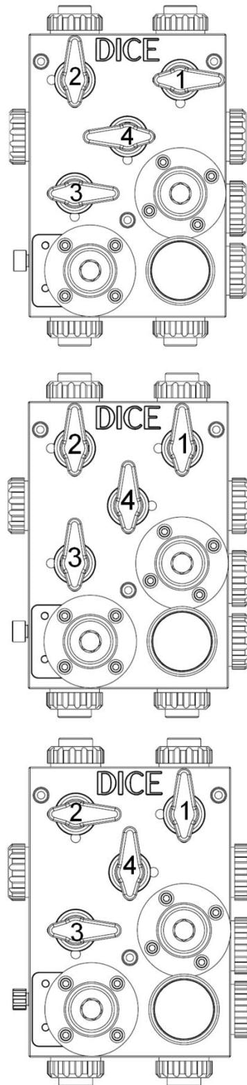 Close the evacuation valve (3) and injection valve (1). Open the calibration column valve (2) and separation valve (4).
Follow your dosing pump manufacturer's calibration procedure.
Close the chemical tank isolation valve (at tank or on pump suction line).
Close the separation valve (4). Open the injection valve (1).
Open the evacuation valve (3) to drain the calibration cylinder.
* **Suction lift**: Contents drain by gravity to tank below
* **Flooded suction**: Start pump to empty contents into process
Close the evacuation valve (3) and calibration column valve (2).
Open the chemical tank isolation valve.
### DM Valve Positions
| Mode | Valve 1 (Injection) | Valve 2 (Calibration) | Valve 3 (Evacuation) | Valve 4 (Separation) |
| ---------------- | ------------------- | --------------------- | -------------------- | -------------------- |
| Calibration | Closed | Open | Closed | Open |
| Draining | Open | Closed | Open | Closed |
| Normal operation | Open | Closed | Closed | Closed |
The top of the calibration column must be vented to atmosphere to enable gravity drainage through the evacuation valve.
## Post-Startup Verification
Confirm the pressure indicator reads the back pressure set point.
Inspect all connections for leaks.
Verify all ball valves are in the correct position for normal operation.
Record the set points for future reference.
If the pressure indicator does not show the expected back pressure reading, refer to [Troubleshooting](/docs/mtc/dice/troubleshooting).
***
## Related Products
1/2" module for suction lift applications
1/2" and 1" modules for flooded suction
## Sources
Pages 18–23 • July 2022
Close the evacuation valve (3) and injection valve (1). Open the calibration column valve (2) and separation valve (4).
Follow your dosing pump manufacturer's calibration procedure.
Close the chemical tank isolation valve (at tank or on pump suction line).
Close the separation valve (4). Open the injection valve (1).
Open the evacuation valve (3) to drain the calibration cylinder.
* **Suction lift**: Contents drain by gravity to tank below
* **Flooded suction**: Start pump to empty contents into process
Close the evacuation valve (3) and calibration column valve (2).
Open the chemical tank isolation valve.
### DM Valve Positions
| Mode | Valve 1 (Injection) | Valve 2 (Calibration) | Valve 3 (Evacuation) | Valve 4 (Separation) |
| ---------------- | ------------------- | --------------------- | -------------------- | -------------------- |
| Calibration | Closed | Open | Closed | Open |
| Draining | Open | Closed | Open | Closed |
| Normal operation | Open | Closed | Closed | Closed |
The top of the calibration column must be vented to atmosphere to enable gravity drainage through the evacuation valve.
## Post-Startup Verification
Confirm the pressure indicator reads the back pressure set point.
Inspect all connections for leaks.
Verify all ball valves are in the correct position for normal operation.
Record the set points for future reference.
If the pressure indicator does not show the expected back pressure reading, refer to [Troubleshooting](/docs/mtc/dice/troubleshooting).
***
## Related Products
1/2" module for suction lift applications
1/2" and 1" modules for flooded suction
## Sources
Pages 18–23 • July 2022