> ## Documentation Index
> Fetch the complete documentation index at: https://docs.supplyline.com/docs/llms.txt
> Use this file to discover all available pages before exploring further.
# Installation
> Mounting, sensor installation, and electrical wiring for the Walchem Intuition-6 controller
# Installation
Source: [Intuition-6 Instruction Manual Rev. H](https://supplyline.com/assets/wal/WAL-IOM_Intuition-6-Instruction-Manual-RevH.pdf), Pages: 11–35
The electrical installation must be performed by qualified personnel and conform to all applicable national, state, and local codes. Live circuits are present inside the controller even when the front panel power switch is OFF.
## Enclosure Mounting
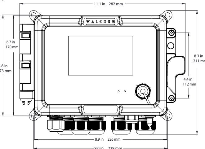
The controller should be wall mounted at eye level on a vibration-free surface using all four mounting holes.
 ### Mounting Requirements
* Use M6 (1/4" diameter) fasteners appropriate for the wall material
* Do not install where the display will be exposed to direct sunlight
* Consider maximum operating ambient temperature of 131°F (55°C)
### Required Clearances
| Side | Clearance |
| ------ | ---------------------------------------------- |
| Top | 2" (50 mm) |
| Left | 8" (203 mm) — not required for prewired models |
| Right | 4" (102 mm) |
| Bottom | 7" (178 mm) |
### Enclosure Dimensions
| Dimension | Inches | Millimeters |
| ------------------------- | ------ | ----------- |
| Width | 11.1 | 282 |
| Height | 8.3 | 211 |
| Depth | 5.5 | 140 |
| Mounting Hole Spacing (W) | 8.9 | 226 |
| Mounting Hole Spacing (H) | 6.7 | 170 |
## Sensor Installation
Use these guidelines to place and mount sensors for accurate readings.
### General Guidelines
Position sensors where:
* An active, representative sample of water is available
* Sensors can easily be removed for cleaning
* Air bubbles will not be trapped within the sensing area
* Sediment or oil will not accumulate on the sensing surfaces
### In-Line Sensor Mounting
For sensors installed in a flow manifold:
Connect to the discharge side of the recirculation pump
Provide minimum 1 GPM flow through the flow switch manifold
Flow must enter from the bottom to close the flow switch
Return line must go to a point of lower pressure to ensure flow
Install isolation valves on both sides for maintenance access
To avoid cracking plastic fittings, use no more than 3 wraps of Teflon tape and thread finger tight plus 1/2 turn only. Do not use pipe dope on flow switch threads.
### Submersion Sensor Mounting
For sensors submerged directly in the process:
1. Mount sensors firmly to the tank
2. Protect cable runs with plastic conduit sealed at the top
3. Position in an area of good solution movement
4. Locate for rapid response to treatment chemicals without seeing injection spikes
### Sensor-Specific Guidelines
Use the sensor-specific notes below to confirm cabling and placement limits.
#### Contacting Conductivity Sensors
* Maximum cable length: 250 ft (76 m); less than 25 ft (8 m) recommended
* Use shielded cable for all extensions
* Maintain 6" (15 cm) separation from AC voltage wiring
#### Electrodeless Conductivity Sensors
* Maximum cable length: 120 ft (37 m); less than 20 ft (6 m) recommended
* Maintain 6" (15 cm) of sample around the sensor
* Keep nearby conductive items consistently positioned
* Do not install in the path of stray electrical currents
#### pH/ORP Electrodes
* Maximum cable length: 1000 ft (305 m) with junction box
* Install with measuring surfaces always wet (U-trap recommended)
* Mount at minimum 5° above horizontal with measuring surface down
* Flow velocity must be less than 10 ft/sec (3 m/sec)
#### Disinfection Sensors
* Maximum cable length: 100 ft (30 m) with junction box
* Flow cell inlet must be from the bottom (3/4" x 1/4" reducing bushing)
* Do not remove the inlet bushing—it provides required flow velocity
* Outlet must vent to atmosphere (max 1 atm back pressure)
* Install with measuring surface down, at least 5° above horizontal
## Boiler Installation
Follow these requirements when installing sensors on boiler systems.
### Important Notes
Review these boiler-side constraints before selecting the sampling location.
1. Minimum water level must be 4-6" above the skimmer blowdown line
2. Maintain 3/4" minimum pipe ID from boiler tap to electrode
3. Use full port valves only—any restriction causes flashing
4. Keep distance from boiler tap to electrode under 10 ft
5. Mount electrode in cross fitting on horizontal pipe run
6. Install flow restriction downstream of electrode and control valve
### Blowdown Sizing
Use the calculation below to size blowdown for your boiler.
#### Determine Blowdown Rate
```
Blowdown Rate (lbs/hr) = Steam Production / (Cycles of Concentration - 1)
```
**Example:** 100 HP boiler = 3,450 lbs/hr steam
At 10 cycles: 3,450 / (10-1) = 383 lbs/hr blowdown
#### Continuous vs. Intermittent Sampling
Use **intermittent sampling** when:
* Boiler operation is intermittent
* Required blowdown rate is less than 25% of smallest valve/orifice capacity
Use **continuous sampling** when:
* Boiler operates 24 hours/day
* Required blowdown rate exceeds 25% of smallest valve/orifice
## Electrical Installation
### Mounting Requirements
* Use M6 (1/4" diameter) fasteners appropriate for the wall material
* Do not install where the display will be exposed to direct sunlight
* Consider maximum operating ambient temperature of 131°F (55°C)
### Required Clearances
| Side | Clearance |
| ------ | ---------------------------------------------- |
| Top | 2" (50 mm) |
| Left | 8" (203 mm) — not required for prewired models |
| Right | 4" (102 mm) |
| Bottom | 7" (178 mm) |
### Enclosure Dimensions
| Dimension | Inches | Millimeters |
| ------------------------- | ------ | ----------- |
| Width | 11.1 | 282 |
| Height | 8.3 | 211 |
| Depth | 5.5 | 140 |
| Mounting Hole Spacing (W) | 8.9 | 226 |
| Mounting Hole Spacing (H) | 6.7 | 170 |
## Sensor Installation
Use these guidelines to place and mount sensors for accurate readings.
### General Guidelines
Position sensors where:
* An active, representative sample of water is available
* Sensors can easily be removed for cleaning
* Air bubbles will not be trapped within the sensing area
* Sediment or oil will not accumulate on the sensing surfaces
### In-Line Sensor Mounting
For sensors installed in a flow manifold:
Connect to the discharge side of the recirculation pump
Provide minimum 1 GPM flow through the flow switch manifold
Flow must enter from the bottom to close the flow switch
Return line must go to a point of lower pressure to ensure flow
Install isolation valves on both sides for maintenance access
To avoid cracking plastic fittings, use no more than 3 wraps of Teflon tape and thread finger tight plus 1/2 turn only. Do not use pipe dope on flow switch threads.
### Submersion Sensor Mounting
For sensors submerged directly in the process:
1. Mount sensors firmly to the tank
2. Protect cable runs with plastic conduit sealed at the top
3. Position in an area of good solution movement
4. Locate for rapid response to treatment chemicals without seeing injection spikes
### Sensor-Specific Guidelines
Use the sensor-specific notes below to confirm cabling and placement limits.
#### Contacting Conductivity Sensors
* Maximum cable length: 250 ft (76 m); less than 25 ft (8 m) recommended
* Use shielded cable for all extensions
* Maintain 6" (15 cm) separation from AC voltage wiring
#### Electrodeless Conductivity Sensors
* Maximum cable length: 120 ft (37 m); less than 20 ft (6 m) recommended
* Maintain 6" (15 cm) of sample around the sensor
* Keep nearby conductive items consistently positioned
* Do not install in the path of stray electrical currents
#### pH/ORP Electrodes
* Maximum cable length: 1000 ft (305 m) with junction box
* Install with measuring surfaces always wet (U-trap recommended)
* Mount at minimum 5° above horizontal with measuring surface down
* Flow velocity must be less than 10 ft/sec (3 m/sec)
#### Disinfection Sensors
* Maximum cable length: 100 ft (30 m) with junction box
* Flow cell inlet must be from the bottom (3/4" x 1/4" reducing bushing)
* Do not remove the inlet bushing—it provides required flow velocity
* Outlet must vent to atmosphere (max 1 atm back pressure)
* Install with measuring surface down, at least 5° above horizontal
## Boiler Installation
Follow these requirements when installing sensors on boiler systems.
### Important Notes
Review these boiler-side constraints before selecting the sampling location.
1. Minimum water level must be 4-6" above the skimmer blowdown line
2. Maintain 3/4" minimum pipe ID from boiler tap to electrode
3. Use full port valves only—any restriction causes flashing
4. Keep distance from boiler tap to electrode under 10 ft
5. Mount electrode in cross fitting on horizontal pipe run
6. Install flow restriction downstream of electrode and control valve
### Blowdown Sizing
Use the calculation below to size blowdown for your boiler.
#### Determine Blowdown Rate
```
Blowdown Rate (lbs/hr) = Steam Production / (Cycles of Concentration - 1)
```
**Example:** 100 HP boiler = 3,450 lbs/hr steam
At 10 cycles: 3,450 / (10-1) = 383 lbs/hr blowdown
#### Continuous vs. Intermittent Sampling
Use **intermittent sampling** when:
* Boiler operation is intermittent
* Required blowdown rate is less than 25% of smallest valve/orifice capacity
Use **continuous sampling** when:
* Boiler operates 24 hours/day
* Required blowdown rate exceeds 25% of smallest valve/orifice
## Electrical Installation
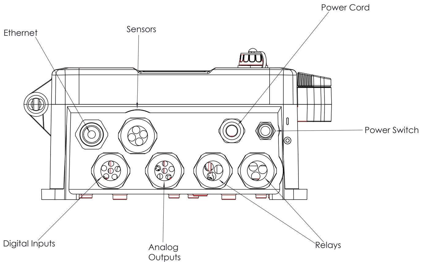 ### Safety Precautions
1. Live circuits exist inside the controller even with power switch OFF
2. Ensure clear access to the disconnecting device
3. Installation must be by trained personnel only
4. Proper grounding is required for safety
### Power Supply Wiring
The controller accepts 100-240 VAC, 50/60 Hz input power.
#### Prewired Models
* Supplied with 8 ft, 18 AWG power cord with USA plug
#### Hardwired Models
| Terminal | Wire Color (120V) | Wire Color (240V) |
| ----------- | ----------------- | ----------------- |
| Line (L) | Black | Brown |
| Neutral (N) | White | Blue |
| Ground | Green | Green/Yellow |
### Relay Output Wiring
### Safety Precautions
1. Live circuits exist inside the controller even with power switch OFF
2. Ensure clear access to the disconnecting device
3. Installation must be by trained personnel only
4. Proper grounding is required for safety
### Power Supply Wiring
The controller accepts 100-240 VAC, 50/60 Hz input power.
#### Prewired Models
* Supplied with 8 ft, 18 AWG power cord with USA plug
#### Hardwired Models
| Terminal | Wire Color (120V) | Wire Color (240V) |
| ----------- | ----------------- | ----------------- |
| Line (L) | Black | Brown |
| Neutral (N) | White | Blue |
| Ground | Green | Green/Yellow |
### Relay Output Wiring
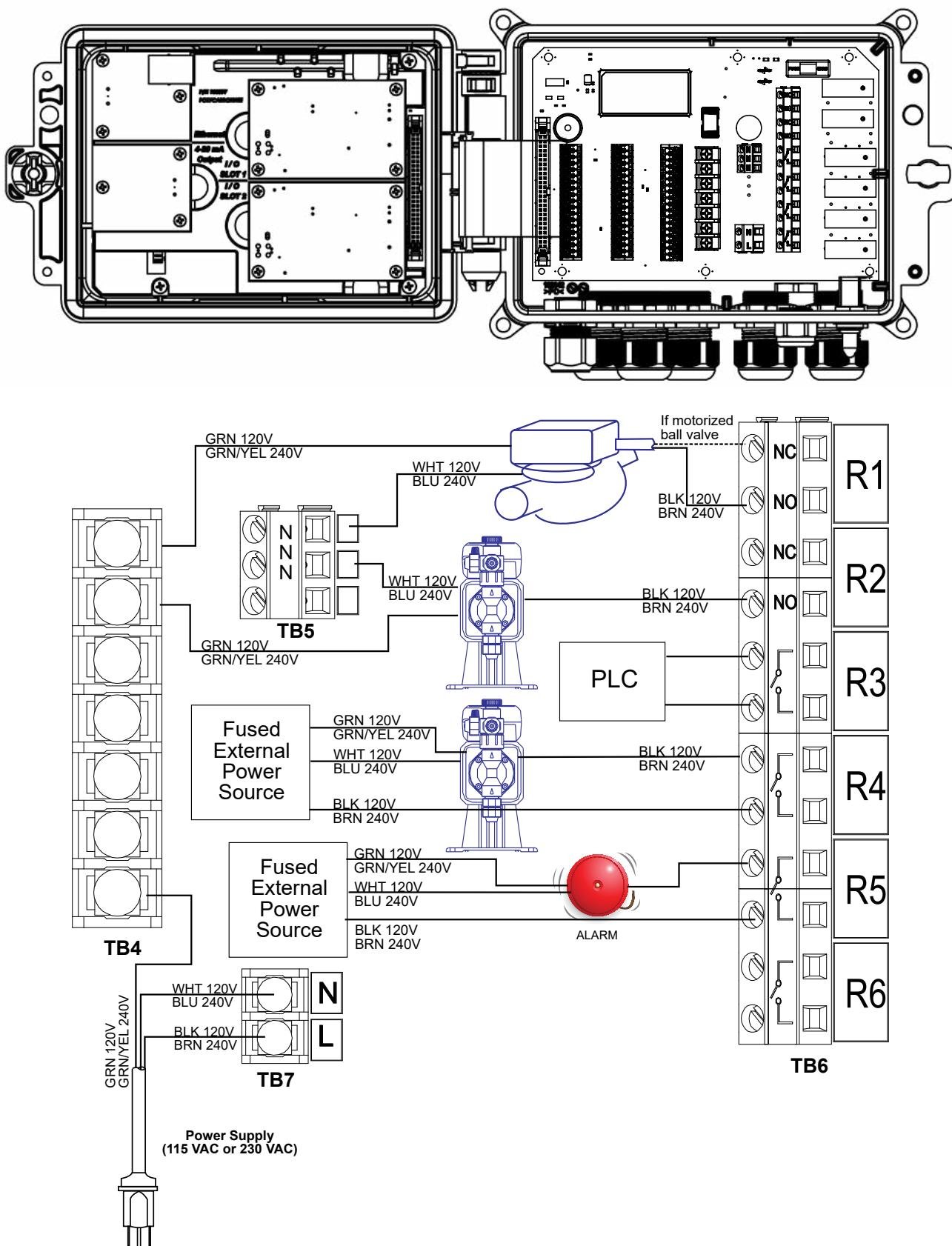 #### Powered Relay Models (W6000, W6A00)
All six relays switch line voltage to external loads.
| Terminal Block | Function |
| -------------- | --------------------------------- |
| TB7 | Power input (Line, Neutral) |
| TB4 | Ground bus |
| TB5 | Neutral distribution |
| TB6 | Relay outputs R1-R6 (NO contacts) |
Connect each load:
1. Switched line from TB6 relay terminal
2. Neutral from TB5
3. Ground to TB4
Total current for all six powered relays must not exceed 6 A. All relays share a common fuse.
#### Dry Contact Relay Models (W6100, W6B00)
Dry contact relays can switch external power sources. Route external power through fused external source terminals.
### Sensor Input Wiring
#### Powered Relay Models (W6000, W6A00)
All six relays switch line voltage to external loads.
| Terminal Block | Function |
| -------------- | --------------------------------- |
| TB7 | Power input (Line, Neutral) |
| TB4 | Ground bus |
| TB5 | Neutral distribution |
| TB6 | Relay outputs R1-R6 (NO contacts) |
Connect each load:
1. Switched line from TB6 relay terminal
2. Neutral from TB5
3. Ground to TB4
Total current for all six powered relays must not exceed 6 A. All relays share a common fuse.
#### Dry Contact Relay Models (W6100, W6B00)
Dry contact relays can switch external power sources. Route external power through fused external source terminals.
### Sensor Input Wiring
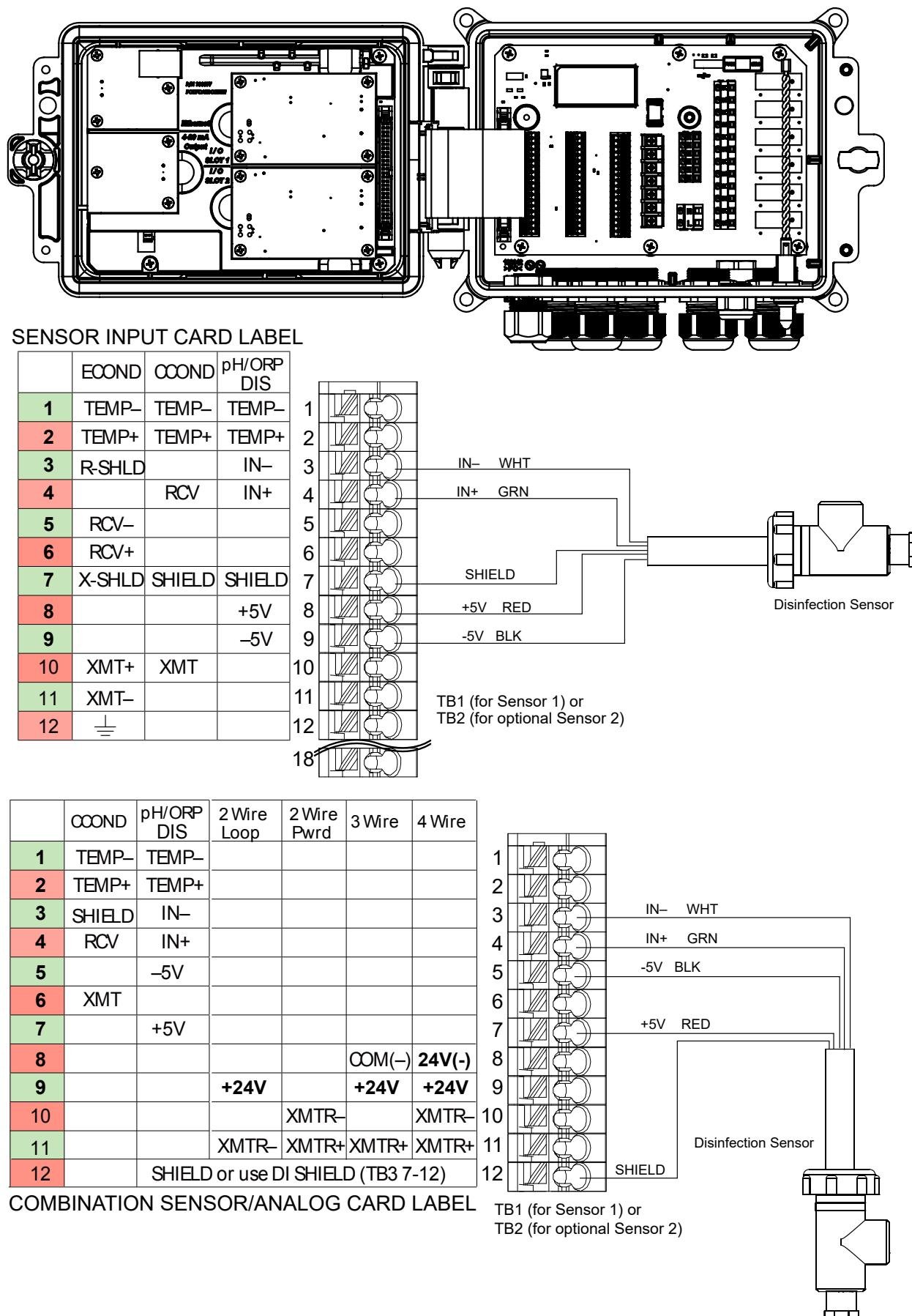 #### Contacting Conductivity
| Terminal | Function | Wire Color |
| -------- | -------- | ---------- |
| 1 | TEMP- | White |
| 2 | TEMP+ | Green |
| 4 | RCV | Black |
| 7 | SHIELD | Shield |
| 10 | XMT | Red |
#### Electrodeless Conductivity
| Terminal | Function | Wire Color |
| -------- | -------- | ---------- |
| 1 | TEMP- | Black |
| 2 | TEMP+ | Green |
| 3 | R-SHLD | Shield |
| 5 | RCV- | Black |
| 6 | RCV+ | Red |
| 7 | X-SHLD | Shield |
| 10 | XMT+ | White |
| 11 | XMT- | Black |
#### pH/ORP/ISE Sensors
| Terminal | Function | Wire Color |
| -------- | -------- | ------------ |
| 1 | TEMP- | White/Green |
| 2 | TEMP+ | Green/White |
| 3 | IN- | White/Orange |
| 4 | IN+ | Orange/White |
| 5 | -5V | White/Blue |
| 7 | SHIELD | Shield |
| 8 | +5V | Blue/White |
#### Disinfection Sensors
| Terminal | Function | Wire Color |
| -------- | -------- | ---------- |
| 3 | IN- | White |
| 4 | IN+ | Green |
| 7 | SHIELD | Shield |
| 8 | +5V | Red |
| 9 | -5V | Black |
### 4-20 mA Transmitter Wiring
#### Contacting Conductivity
| Terminal | Function | Wire Color |
| -------- | -------- | ---------- |
| 1 | TEMP- | White |
| 2 | TEMP+ | Green |
| 4 | RCV | Black |
| 7 | SHIELD | Shield |
| 10 | XMT | Red |
#### Electrodeless Conductivity
| Terminal | Function | Wire Color |
| -------- | -------- | ---------- |
| 1 | TEMP- | Black |
| 2 | TEMP+ | Green |
| 3 | R-SHLD | Shield |
| 5 | RCV- | Black |
| 6 | RCV+ | Red |
| 7 | X-SHLD | Shield |
| 10 | XMT+ | White |
| 11 | XMT- | Black |
#### pH/ORP/ISE Sensors
| Terminal | Function | Wire Color |
| -------- | -------- | ------------ |
| 1 | TEMP- | White/Green |
| 2 | TEMP+ | Green/White |
| 3 | IN- | White/Orange |
| 4 | IN+ | Orange/White |
| 5 | -5V | White/Blue |
| 7 | SHIELD | Shield |
| 8 | +5V | Blue/White |
#### Disinfection Sensors
| Terminal | Function | Wire Color |
| -------- | -------- | ---------- |
| 3 | IN- | White |
| 4 | IN+ | Green |
| 7 | SHIELD | Shield |
| 8 | +5V | Red |
| 9 | -5V | Black |
### 4-20 mA Transmitter Wiring
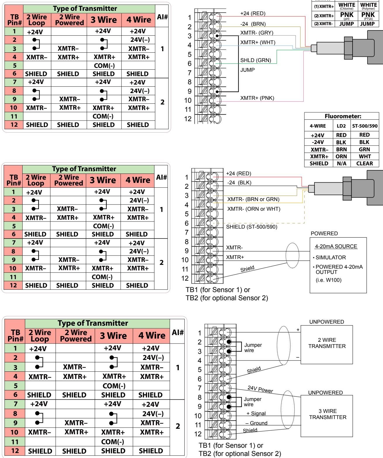 | Terminal | Connection |
| --------- | ---------- |
| 1 (or 7) | +24V |
| 4 (or 10) | XMTR- |
Jumper between terminals 2-3 (or 8-9).
| Terminal | Connection |
| --------- | ---------- |
| 3 (or 9) | XMTR+ |
| 4 (or 10) | XMTR- |
| Terminal | Connection |
| --------- | ---------- |
| 1 (or 7) | +24V |
| 4 (or 10) | XMTR+ |
| 5 (or 11) | COM(-) |
| Terminal | Connection |
| --------- | ---------- |
| 1 (or 7) | +24V |
| 2 (or 8) | 24V(-) |
| 3 (or 9) | XMTR- |
| 4 (or 10) | XMTR+ |
### Digital Input Wiring
| Terminal | Connection |
| --------- | ---------- |
| 1 (or 7) | +24V |
| 4 (or 10) | XMTR- |
Jumper between terminals 2-3 (or 8-9).
| Terminal | Connection |
| --------- | ---------- |
| 3 (or 9) | XMTR+ |
| 4 (or 10) | XMTR- |
| Terminal | Connection |
| --------- | ---------- |
| 1 (or 7) | +24V |
| 4 (or 10) | XMTR+ |
| 5 (or 11) | COM(-) |
| Terminal | Connection |
| --------- | ---------- |
| 1 (or 7) | +24V |
| 2 (or 8) | 24V(-) |
| 3 (or 9) | XMTR- |
| 4 (or 10) | XMTR+ |
### Digital Input Wiring
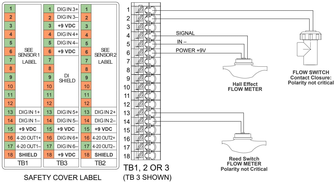 | Input | Terminals | Function |
| ----- | --------------- | -------------------------- |
| DI 1 | TB1: 13, 14, 15 | High or low speed counter |
| DI 2 | TB2: 13, 14, 15 | High or low speed counter |
| DI 3 | TB3: 1, 2, 3 | State or low speed counter |
| DI 4 | TB3: 4, 5, 6 | State or low speed counter |
| DI 5 | TB3: 13, 14, 15 | High or low speed counter |
| DI 6 | TB3: 16, 17, 18 | State or low speed counter |
#### Flow Switch (Dry Contact)
Connect to DI+ and DI- terminals. Polarity not critical.
#### Hall Effect Flow Meter
| Terminal | Connection |
| -------- | ---------- |
| DI+ | Signal |
| DI- | Ground |
| +9VDC | Power |
### Analog Output Wiring
| Terminal Block | Connection |
| --------------- | ------------------ |
| TB1: 16, 17, 18 | AO1 (+, -, Shield) |
| TB2: 16, 17, 18 | AO2 (+, -, Shield) |
### Wiring Best Practices
Use stranded, twisted, shielded pair wire (22-26 AWG) for:
* Flow meter contactor inputs
* 4-20 mA outputs
* Remote flow switches
Terminate shield at the controller end only.
Route sensor cables at least 6" from AC power wiring
Use proper cable glands and strain relief at enclosure entry points
Keep cable runs as short as practical to reduce noise pickup
Label all wires for future reference and troubleshooting
Before powering on the controller, verify all wiring connections with a multimeter. Incorrect wiring can damage sensors or controller inputs.
## Sources
Pages 11–35 • February 2024
| Input | Terminals | Function |
| ----- | --------------- | -------------------------- |
| DI 1 | TB1: 13, 14, 15 | High or low speed counter |
| DI 2 | TB2: 13, 14, 15 | High or low speed counter |
| DI 3 | TB3: 1, 2, 3 | State or low speed counter |
| DI 4 | TB3: 4, 5, 6 | State or low speed counter |
| DI 5 | TB3: 13, 14, 15 | High or low speed counter |
| DI 6 | TB3: 16, 17, 18 | State or low speed counter |
#### Flow Switch (Dry Contact)
Connect to DI+ and DI- terminals. Polarity not critical.
#### Hall Effect Flow Meter
| Terminal | Connection |
| -------- | ---------- |
| DI+ | Signal |
| DI- | Ground |
| +9VDC | Power |
### Analog Output Wiring
| Terminal Block | Connection |
| --------------- | ------------------ |
| TB1: 16, 17, 18 | AO1 (+, -, Shield) |
| TB2: 16, 17, 18 | AO2 (+, -, Shield) |
### Wiring Best Practices
Use stranded, twisted, shielded pair wire (22-26 AWG) for:
* Flow meter contactor inputs
* 4-20 mA outputs
* Remote flow switches
Terminate shield at the controller end only.
Route sensor cables at least 6" from AC power wiring
Use proper cable glands and strain relief at enclosure entry points
Keep cable runs as short as practical to reduce noise pickup
Label all wires for future reference and troubleshooting
Before powering on the controller, verify all wiring connections with a multimeter. Incorrect wiring can damage sensors or controller inputs.
## Sources
Pages 11–35 • February 2024