> ## Documentation Index
> Fetch the complete documentation index at: https://docs.supplyline.com/docs/llms.txt
> Use this file to discover all available pages before exploring further.
# Operation
> Touchscreen interface navigation, sensor calibration, and daily operation of the Walchem Intuition-6 controller
# Operation
Source: [Intuition-6 Instruction Manual Rev. H](https://supplyline.com/assets/wal/WAL-IOM_Intuition-6-Instruction-Manual-RevH.pdf), Pages: 36–64
The Intuition-6 features a 5" color touchscreen for all configuration and monitoring functions.
## Front Panel
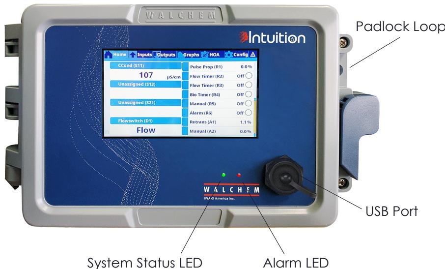 | Component | Function |
| ----------------------- | ---------------------------------------------------- |
| **Power Switch** | On/Off rocker switch (circuits remain live when off) |
| **Touchscreen Display** | 800 x 480 pixel capacitive touchscreen |
| **System Status LED** | Green = running normally |
| **Alarm LED** | Red = active alarm |
| **USB Port** | Firmware upgrades, config backup, datalog export |
| **Padlock Loop** | Security lockout for enclosure door |
## Startup
Turn on the power switch. The display will show the Walchem logo during initialization.
On first startup, configure:
* Date and time
* Language preference
* Input and output assignments
Check that all connected sensors display valid readings on the home screen.
Configure each relay for the desired control mode before placing in Auto.
## Shutdown
For planned shutdowns:
Place all relay outputs in Off mode via the HOA menu
Wait for any active processes to complete (biocide timers, bleed cycles)
Turn off the power switch on the front panel
Disconnect power at the source if servicing the controller
The power switch does not disconnect all internal circuits. Always disconnect external power before opening the enclosure.
## Home Screen
The home screen displays a customizable summary of inputs and outputs. Touch any displayed value to access its detail screen.
### Customizing the Home Screen
1. Press and hold anywhere on the home screen for 3 seconds
2. Use the Edit icons to:
* **Split** cells to show more items
* **Merge** cells to show fewer, larger items
* **Move** items up or down
* **Delete** items from display
3. Touch the checkmark to save changes
## Screen Icons
| Icon | Function |
| ------------------------ | ------------------------------ |
| Calibration (target) | Access sensor calibration |
| Graph (line chart) | View sensor trend graph |
| Edit (pencil) | Modify settings |
| Info (i in circle) | Return to view mode |
| Close (X) | Close menu, return to previous |
| Confirm (checkmark) | Save changes |
| Filter (funnel) | Limit displayed choices |
| Delete (backspace arrow) | Erase character entry |
## Menu Structure
Displays all active and recent alarms. Touch any alarm for details.
**Alarm Types:**
* Sensor alarms (Hi/Hi, Hi, Lo, Lo/Lo)
* Output timeout alarms
* Flow verify alarms
* Communication errors
* Calibration reminders
Lists all configured sensor inputs. Touch any input to:
* View current value and status
* Access calibration
* View trend graph
* Edit settings
Lists all relay and analog outputs. Touch any output to:
* View current state (On/Off, % output)
* View accumulated on-time
* Change HOA (Hand-Off-Auto) state
* Edit control parameters
Access system-wide settings:
* **Global Settings** — Date/time, language, display format
* **Security Settings** — Passwords and access levels
* **Ethernet Settings** — Network configuration
* **Remote Communications** — Modbus/BACnet setup
* **Email Reports** — Alert and datalog recipients
* **Display Settings** — Brightness, auto-dim, screen timeout
* **File Utilities** — USB backup and restore
Quick access to Hand-Off-Auto settings for all outputs:
* **Hand** — Test outputs manually
* **Off** — Disable outputs
* **Auto** — Return to automatic control
View trend graphs for any sensor input:
* Configure time range and Y-axis scale
* Display multiple inputs on one graph
* Pinch to zoom, drag to pan
## Hand-Off-Auto (HOA) Control
Each output can be set to one of three states:
| State | Description |
| -------- | -------------------------------------------- |
| **Hand** | Output forced ON regardless of control mode |
| **Off** | Output forced OFF regardless of control mode |
| **Auto** | Output controlled by programmed algorithm |
Hand Time Limit can be configured to automatically return an output from Hand to its previous state after a set time—prevents forgetting a pump in manual mode.
## Sensor Calibration
Calibration maintains measurement accuracy. Access calibration from the Input menu by touching the calibration icon.
**One-Point Process Calibration:**
Take a grab sample while viewing the live reading
Measure sample conductivity with a lab meter
Enter the lab value in the controller
Touch Confirm to save calibration
**One-Point Buffer Calibration:**
Place sensor in known conductivity solution
Enter solution value
Wait for reading to stabilize
Touch Confirm to save calibration
**Two-Point Buffer Calibration (Recommended):**
Rinse sensor and place in first buffer (e.g., pH 7)
Wait for stabilization, then touch Confirm
Rinse sensor and place in second buffer (e.g., pH 4 or 10)
Wait for stabilization
Review slope and offset values, then Confirm to save
**Acceptable pH Sensor Values:**
| Parameter | Good | Marginal | Replace |
| --------- | ----------- | ----------- | ---------- |
| Slope | 54-62 mV/pH | 48-54 mV/pH | \<48 mV/pH |
| Offset | ±30 mV | ±50 mV | >±50 mV |
Ideal slope is 59.16 mV/pH at 25°C. Declining slope indicates aging electrode.
**One-Point Calibration:**
Place sensor in ORP reference solution (e.g., 225 mV)
Enter solution value
Wait for stabilization
Touch Confirm to save
ORP calibration is typically only needed to verify sensor function. Many applications use uncalibrated ORP readings since relative changes matter more than absolute values.
**Process Calibration:**
Take grab sample during stable conditions
Measure free chlorine with DPD test kit
Enter measured value in controller
Touch Confirm to save
**Zero Calibration:**
Place sensor in chlorine-free water
Set value to 0
Touch Confirm to save
**Two-Point Calibration (Recommended):**
Set transmitter to low point (e.g., 4 mA)
Enter value and touch Confirm
Set transmitter to high point (e.g., 20 mA)
Enter value and touch Confirm
**One-Point Calibration:**
For minor offset corrections, set transmitter to any known mA value and enter that value in the controller.
## Sensor Settings
Each sensor type has configurable parameters:
### Common Settings
| Setting | Description |
| ------------------ | ------------------------------------------ |
| Alarms | Lo/Lo, Lo, Hi, Hi/Hi thresholds |
| Deadband | Difference between alarm on and off points |
| Smoothing Factor | 0-90%, damping for noisy signals |
| Cal Required Alarm | Days between calibration reminders |
| Name | Custom identifier for the input |
### Conductivity-Specific
| Setting | Description |
| ----------------- | -------------------------------------- |
| Cell Constant | Match to sensor (0.01, 0.1, 1.0, 10.0) |
| Temp Compensation | NaCl standard or Linear %/°C |
| Temp Comp Factor | Linear coefficient (typically 2%/°C) |
| Default Temp | Temperature used if sensor fails |
| Cable Length | For compensation of long cable runs |
| Units | µS/cm, mS/cm, mS/m, S/m, or ppm |
### pH-Specific
| Setting | Description |
| ------------ | ------------------------------------------ |
| Buffers | Manual, JIS/NIST, DIN, or Traceable 4/7/10 |
| Electrode | Glass (standard) or Antimony |
| Default Temp | Temperature if sensor fails |
### 4-20 mA Transmitter
| Setting | Description |
| ---------------- | ------------------------------------------- |
| Transmitter Type | 2-wire loop, 2-wire powered, 3-wire, 4-wire |
| 4 mA Value | Engineering units at 4 mA |
| 20 mA Value | Engineering units at 20 mA |
| Units | Custom units text |
## Digital Input Configuration
Configure each digital input type using the settings below.
### DI State (Flow Switch/Interlock)
| Setting | Description |
| -------------- | ---------------------------------------- |
| Open Message | Text shown when switch open |
| Closed Message | Text shown when switch closed |
| Interlock | Which state triggers interlock |
| Alarm | Generate alarm on Open, Closed, or Never |
### Flow Meter (Contactor)
| Setting | Description |
| --------------- | ---------------------------------- |
| Volume/Contact | Volume per switch closure |
| Flow Units | Gallons, Liters, m³, MG |
| Totalizer Alarm | Alarm when total exceeds value |
| Scheduled Reset | Daily, Monthly, Annually, or Never |
### Flow Meter (Paddlewheel)
| Setting | Description |
| --------------- | ----------------------------- |
| K Factor | Pulses per unit volume |
| Flow/Rate Units | Volume and time base |
| Alarms | Low and High flow rate limits |
### Feed Monitor
| Setting | Description |
| ---------------- | ---------------------------------- |
| Volume/Contact | Volume per pulse (from pump specs) |
| Totalizer Alarm | Maximum allowed total |
| Flow Alarm Delay | Time before loss-of-flow alarm |
| Flow Alarm Clear | Pulses required to clear alarm |
| Reprime Time | Pump on-time when loss detected |
| Linked Output | Which relay controls this pump |
## Ethernet Configuration
Use these settings to connect the controller to the network and enable web/email features.
### Network Setup
1. Go to Configuration → Ethernet Settings
2. Select DHCP or enter fixed IP address
3. Configure subnet mask and gateway
4. Test connection
### Web Interface Access
1. Connect controller to network
2. Enter IP address in web browser
3. Log in with controller password
4. Access all configuration via web pages
### Email Configuration
Configure up to 8 email addresses for:
* Alarm notifications
* Periodic datalog reports
* Calibration reminders
Email requires SMTP server configuration. Contact your IT department for the correct settings.
## USB Functions
Insert a USB flash drive to access:
### Software Upgrade
1. Download latest firmware from Walchem website
2. Copy to USB drive root directory
3. Insert drive, navigate to File Utilities
4. Select Software Upgrade
### Config File Backup/Restore
1. Export configuration to USB
2. Import to another controller for quick setup
3. Useful for multi-controller installations
### Datalog Export
1. Select date range
2. Export to CSV format
3. Open in Excel or similar spreadsheet
## Sources
Pages 36–64 • February 2024
| Component | Function |
| ----------------------- | ---------------------------------------------------- |
| **Power Switch** | On/Off rocker switch (circuits remain live when off) |
| **Touchscreen Display** | 800 x 480 pixel capacitive touchscreen |
| **System Status LED** | Green = running normally |
| **Alarm LED** | Red = active alarm |
| **USB Port** | Firmware upgrades, config backup, datalog export |
| **Padlock Loop** | Security lockout for enclosure door |
## Startup
Turn on the power switch. The display will show the Walchem logo during initialization.
On first startup, configure:
* Date and time
* Language preference
* Input and output assignments
Check that all connected sensors display valid readings on the home screen.
Configure each relay for the desired control mode before placing in Auto.
## Shutdown
For planned shutdowns:
Place all relay outputs in Off mode via the HOA menu
Wait for any active processes to complete (biocide timers, bleed cycles)
Turn off the power switch on the front panel
Disconnect power at the source if servicing the controller
The power switch does not disconnect all internal circuits. Always disconnect external power before opening the enclosure.
## Home Screen
The home screen displays a customizable summary of inputs and outputs. Touch any displayed value to access its detail screen.
### Customizing the Home Screen
1. Press and hold anywhere on the home screen for 3 seconds
2. Use the Edit icons to:
* **Split** cells to show more items
* **Merge** cells to show fewer, larger items
* **Move** items up or down
* **Delete** items from display
3. Touch the checkmark to save changes
## Screen Icons
| Icon | Function |
| ------------------------ | ------------------------------ |
| Calibration (target) | Access sensor calibration |
| Graph (line chart) | View sensor trend graph |
| Edit (pencil) | Modify settings |
| Info (i in circle) | Return to view mode |
| Close (X) | Close menu, return to previous |
| Confirm (checkmark) | Save changes |
| Filter (funnel) | Limit displayed choices |
| Delete (backspace arrow) | Erase character entry |
## Menu Structure
Displays all active and recent alarms. Touch any alarm for details.
**Alarm Types:**
* Sensor alarms (Hi/Hi, Hi, Lo, Lo/Lo)
* Output timeout alarms
* Flow verify alarms
* Communication errors
* Calibration reminders
Lists all configured sensor inputs. Touch any input to:
* View current value and status
* Access calibration
* View trend graph
* Edit settings
Lists all relay and analog outputs. Touch any output to:
* View current state (On/Off, % output)
* View accumulated on-time
* Change HOA (Hand-Off-Auto) state
* Edit control parameters
Access system-wide settings:
* **Global Settings** — Date/time, language, display format
* **Security Settings** — Passwords and access levels
* **Ethernet Settings** — Network configuration
* **Remote Communications** — Modbus/BACnet setup
* **Email Reports** — Alert and datalog recipients
* **Display Settings** — Brightness, auto-dim, screen timeout
* **File Utilities** — USB backup and restore
Quick access to Hand-Off-Auto settings for all outputs:
* **Hand** — Test outputs manually
* **Off** — Disable outputs
* **Auto** — Return to automatic control
View trend graphs for any sensor input:
* Configure time range and Y-axis scale
* Display multiple inputs on one graph
* Pinch to zoom, drag to pan
## Hand-Off-Auto (HOA) Control
Each output can be set to one of three states:
| State | Description |
| -------- | -------------------------------------------- |
| **Hand** | Output forced ON regardless of control mode |
| **Off** | Output forced OFF regardless of control mode |
| **Auto** | Output controlled by programmed algorithm |
Hand Time Limit can be configured to automatically return an output from Hand to its previous state after a set time—prevents forgetting a pump in manual mode.
## Sensor Calibration
Calibration maintains measurement accuracy. Access calibration from the Input menu by touching the calibration icon.
**One-Point Process Calibration:**
Take a grab sample while viewing the live reading
Measure sample conductivity with a lab meter
Enter the lab value in the controller
Touch Confirm to save calibration
**One-Point Buffer Calibration:**
Place sensor in known conductivity solution
Enter solution value
Wait for reading to stabilize
Touch Confirm to save calibration
**Two-Point Buffer Calibration (Recommended):**
Rinse sensor and place in first buffer (e.g., pH 7)
Wait for stabilization, then touch Confirm
Rinse sensor and place in second buffer (e.g., pH 4 or 10)
Wait for stabilization
Review slope and offset values, then Confirm to save
**Acceptable pH Sensor Values:**
| Parameter | Good | Marginal | Replace |
| --------- | ----------- | ----------- | ---------- |
| Slope | 54-62 mV/pH | 48-54 mV/pH | \<48 mV/pH |
| Offset | ±30 mV | ±50 mV | >±50 mV |
Ideal slope is 59.16 mV/pH at 25°C. Declining slope indicates aging electrode.
**One-Point Calibration:**
Place sensor in ORP reference solution (e.g., 225 mV)
Enter solution value
Wait for stabilization
Touch Confirm to save
ORP calibration is typically only needed to verify sensor function. Many applications use uncalibrated ORP readings since relative changes matter more than absolute values.
**Process Calibration:**
Take grab sample during stable conditions
Measure free chlorine with DPD test kit
Enter measured value in controller
Touch Confirm to save
**Zero Calibration:**
Place sensor in chlorine-free water
Set value to 0
Touch Confirm to save
**Two-Point Calibration (Recommended):**
Set transmitter to low point (e.g., 4 mA)
Enter value and touch Confirm
Set transmitter to high point (e.g., 20 mA)
Enter value and touch Confirm
**One-Point Calibration:**
For minor offset corrections, set transmitter to any known mA value and enter that value in the controller.
## Sensor Settings
Each sensor type has configurable parameters:
### Common Settings
| Setting | Description |
| ------------------ | ------------------------------------------ |
| Alarms | Lo/Lo, Lo, Hi, Hi/Hi thresholds |
| Deadband | Difference between alarm on and off points |
| Smoothing Factor | 0-90%, damping for noisy signals |
| Cal Required Alarm | Days between calibration reminders |
| Name | Custom identifier for the input |
### Conductivity-Specific
| Setting | Description |
| ----------------- | -------------------------------------- |
| Cell Constant | Match to sensor (0.01, 0.1, 1.0, 10.0) |
| Temp Compensation | NaCl standard or Linear %/°C |
| Temp Comp Factor | Linear coefficient (typically 2%/°C) |
| Default Temp | Temperature used if sensor fails |
| Cable Length | For compensation of long cable runs |
| Units | µS/cm, mS/cm, mS/m, S/m, or ppm |
### pH-Specific
| Setting | Description |
| ------------ | ------------------------------------------ |
| Buffers | Manual, JIS/NIST, DIN, or Traceable 4/7/10 |
| Electrode | Glass (standard) or Antimony |
| Default Temp | Temperature if sensor fails |
### 4-20 mA Transmitter
| Setting | Description |
| ---------------- | ------------------------------------------- |
| Transmitter Type | 2-wire loop, 2-wire powered, 3-wire, 4-wire |
| 4 mA Value | Engineering units at 4 mA |
| 20 mA Value | Engineering units at 20 mA |
| Units | Custom units text |
## Digital Input Configuration
Configure each digital input type using the settings below.
### DI State (Flow Switch/Interlock)
| Setting | Description |
| -------------- | ---------------------------------------- |
| Open Message | Text shown when switch open |
| Closed Message | Text shown when switch closed |
| Interlock | Which state triggers interlock |
| Alarm | Generate alarm on Open, Closed, or Never |
### Flow Meter (Contactor)
| Setting | Description |
| --------------- | ---------------------------------- |
| Volume/Contact | Volume per switch closure |
| Flow Units | Gallons, Liters, m³, MG |
| Totalizer Alarm | Alarm when total exceeds value |
| Scheduled Reset | Daily, Monthly, Annually, or Never |
### Flow Meter (Paddlewheel)
| Setting | Description |
| --------------- | ----------------------------- |
| K Factor | Pulses per unit volume |
| Flow/Rate Units | Volume and time base |
| Alarms | Low and High flow rate limits |
### Feed Monitor
| Setting | Description |
| ---------------- | ---------------------------------- |
| Volume/Contact | Volume per pulse (from pump specs) |
| Totalizer Alarm | Maximum allowed total |
| Flow Alarm Delay | Time before loss-of-flow alarm |
| Flow Alarm Clear | Pulses required to clear alarm |
| Reprime Time | Pump on-time when loss detected |
| Linked Output | Which relay controls this pump |
## Ethernet Configuration
Use these settings to connect the controller to the network and enable web/email features.
### Network Setup
1. Go to Configuration → Ethernet Settings
2. Select DHCP or enter fixed IP address
3. Configure subnet mask and gateway
4. Test connection
### Web Interface Access
1. Connect controller to network
2. Enter IP address in web browser
3. Log in with controller password
4. Access all configuration via web pages
### Email Configuration
Configure up to 8 email addresses for:
* Alarm notifications
* Periodic datalog reports
* Calibration reminders
Email requires SMTP server configuration. Contact your IT department for the correct settings.
## USB Functions
Insert a USB flash drive to access:
### Software Upgrade
1. Download latest firmware from Walchem website
2. Copy to USB drive root directory
3. Insert drive, navigate to File Utilities
4. Select Software Upgrade
### Config File Backup/Restore
1. Export configuration to USB
2. Import to another controller for quick setup
3. Useful for multi-controller installations
### Datalog Export
1. Select date range
2. Export to CSV format
3. Open in Excel or similar spreadsheet
## Sources
Pages 36–64 • February 2024