Operation
Source: DICE IOM Manual V12E, Pages: 24–30 Use this section to confirm valve positions, operating modes, and safe depressurization steps.Normal Operation
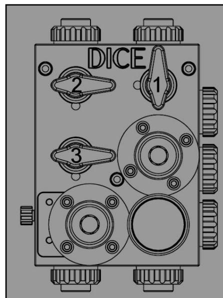
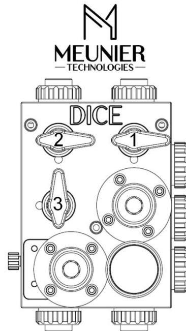
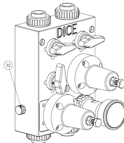
During normal injection operation:| Valve | Position |
|---|---|
| Injection (1) | Open |
| Calibration column (2) | Closed |
| Evacuation (3) | Closed |
| Separation (4) — DM only | Closed |
During normal operation, the pressure indicator should display the back pressure valve set point. If the reading differs significantly, refer to Troubleshooting.
Operating Modes
- Injecting
- Calibration — Filling
- Calibration — Emptying
- Pressure Relief
Chemical flows from the tank through the pump, into the DICE module, through the back pressure valve, and out the injection port to the process.
| Model | Flow Path | Return Path |
|---|---|---|
| DS | Tank → Pump → Module → BPV → Process | Bleed/PRV → Tank |
| DM | Tank → Pump → Module → BPV → Process | Option 1: Pump return. Option 2: Tank |
Ball Valve Guidelines
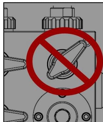
Why full open/closed only?
Why full open/closed only?
- Partial opening causes uneven wear on PTFE valve seats
- Damaged seats lead to leakage in the closed position
- Throttling reduces valve service life
- Always move valves to fully open or fully closed
- If a valve feels stiff, operate it several times to reseat
- Never force a valve—if excessive torque is required, refer to Troubleshooting
Lockout Procedures
DICE modules can be ordered with optional lockout handles, or lockout kits can be purchased separately.
Depressurizing the DICE Module
- Downstream of BPV
- Upstream of BPV
Important depressurization notes
Important depressurization notes
- This procedure depressurizes only the DICE internal cavities
- Chemical pressure may still exist downstream of closed ball valves (e.g., process pressure downstream of closed injection valve)
- Release all downstream pressure before disconnecting piping
- For flooded suction applications, drain the pump suction line before depressurizing the DICE module
Related Products
DICE DS — Suction Lift
1/2” module for suction lift applications
DICE DM — Flooded Suction
1/2” and 1” modules for flooded suction
Sources
DICE IOM Manual V12E
Pages 24–30 • July 2022