Parts List
Source: DICE IOM Manual V12E, Pages: 13, 38 Use this list to identify replacement components, assemblies, and kits.Complete Parts Reference
| Part No. | Description |
|---|---|
| 1 | Mono block |
| 2 | Carrier |
| 3 | Stem |
| 4 | Ball |
| 5 | Stem nut |
| 6 | Seat |
| 7 | O-ring — Carrier |
| 8 | O-ring — Seat |
| 9 | O-ring — Stem |
| 10 | O-ring — Stem nut |
| 11 | Valve handle |
| 12 | Handle set screw |
| 13 | BP/PR top body |
| 14 | Spring bottom seat |
| 15 | Spring top seat |
| 16 | Diaphragm |
| 17 | Spring |
| 18 | Socket head screw |
| 19 | Adjustment screw |
| 20 | Hex nut |
| 21 | PR/BP washer |
| 22 | Sleeve cone adapter |
| 23 | O-ring — Sleeve cone adapter |
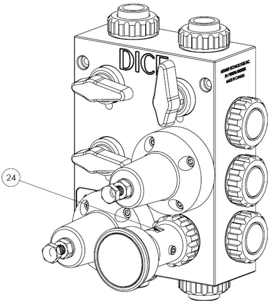
| 24 | Isolator and pressure gauge |
| 25 | Mushroom nut |
| 26 | Connector socket |
| 27 | Connector NPT |
| 28 | Connector hose |
| 29 | Cap |
| 30 | O-ring — Connector |
| 31 | Mounting washer |
| 32 | Bleed valve |
| 33 | O-ring — Bleed valve |
Part numbers 25, 26, and 27 are examples. All connector configurations are listed in the Specifications model number nomenclature section.
Assembly Breakdowns
Ball Valve Assembly
Ball Valve Assembly
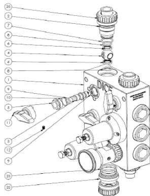
| Part No. | Description | Qty per Valve |
|---|---|---|
| 2 | Carrier | 1 |
| 3 | Stem | 1 |
| 4 | Ball | 1 |
| 5 | Stem nut | 1 |
| 6 | Seat | 2 |
| 7 | O-ring — Carrier | 1 |
| 8 | O-ring — Seat | 2 |
| 9 | O-ring — Stem | 1 |
| 10 | O-ring — Stem nut | 1 |
| 11 | Valve handle | 1 |
| 12 | Handle set screw | 1 |
| 22 | Sleeve cone adapter | 1 (evacuation valve only) |
| 23 | O-ring — Sleeve cone | 1 (evacuation valve only) |
| Model | Ball Valves | Notes |
|---|---|---|
| DICE DS | 3 | Injection, Calibration, Evacuation |
| DICE DM | 4 | Adds Separation valve |
Pressure Relief / Back Pressure Valve Assembly
Pressure Relief / Back Pressure Valve Assembly
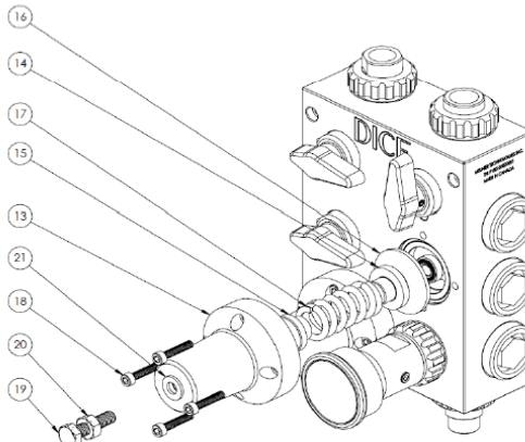
| Part No. | Description | Qty per Valve |
|---|---|---|
| 13 | Regulating valve body | 1 |
| 14 | Spring bottom seat | 1 |
| 15 | Spring top seat | 1 |
| 16 | Diaphragm | 1 |
| 17 | Spring | 1 |
| 18 | Socket head screw | 4 |
| 19 | Adjustment screw | 1 |
| 20 | Hex nut (counter nut) | 1 |
| 21 | Washer | 1 |
Each DICE module includes two regulating valves: one pressure relief valve (PRV) and one back pressure valve (BPV). Components are identical for both.
Connection Components
Connection Components
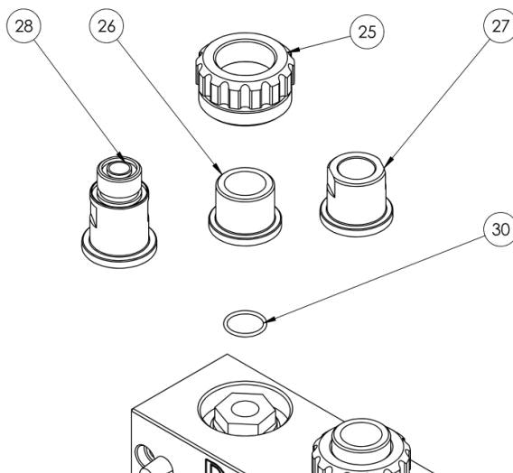
| Part No. | Description |
|---|---|
| 25 | Mushroom nut |
| 26 | Connector socket |
| 27 | Connector NPT |
| 28 | Connector hose |
| 29 | Cap |
| 30 | O-ring — Connector |
Bleed Valve Assembly
Bleed Valve Assembly
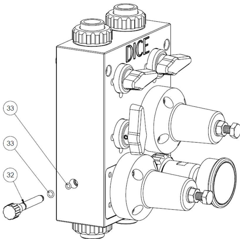
| Part No. | Description | Qty |
|---|---|---|
| 32 | Bleed valve | 1 |
| 33 | O-ring — Bleed valve | 2 |
Pressure Indicator Assembly
Pressure Indicator Assembly
| Part No. | Description | Notes |
|---|---|---|
| 24 | Isolator and pressure gauge assembly | Factory-assembled unit; do not disassemble on site |
Spare Parts Kits
- Ball Valve Kit
- Regulating Valve Kit
- Connector Kit
- O-ring Kit
Contains: Seats (6), O-rings (7, 8, 9, 10), ball (4)
Ordering Spare Parts
When ordering parts, provide:
Material Options
Parts are available in multiple materials. Specify when ordering:Available materials
Available materials
Related Products
DICE DS — Suction Lift
1/2” module for suction lift applications
DICE DM — Flooded Suction
1/2” and 1” modules for flooded suction
Sources
DICE IOM Manual V12E
Pages 13, 38 • July 2022